


Finishing up with combinational circuit design exercises in System Verilog. This time we are going to do exercises on another representation of numbers, BCD (binary-coded decimal format)
Table of Contents
SystemVerilog Study Notes Chapters
- Gate-Level Combinational Circuit
- RTL Combinational Circuit Operators
- RTL Combinational Circuit - Concurrent and Control Constructs
- Hex-Digit to Seven-Segment LED Decoder RTL Combinational Circuit
- Barrel Shifter RTL Combinational Circuit
- Simplified Floating Point Arithmetic. RTL Combinational Circuit
- BCD Number Format. RTL Combinational Circuit
- DDFS. Direct Digital Frequency Synthesis for Sound
- FPGA ADSR envelope generator for sound synthesis
- AMD Xilinx 7 series FPGAs XADC
- Building FPGA-Based Music Instrument Synthesis: A Simple Test Bench Solution
Binary-coded decimal
Binary-coded decimal (BCD) is a class of binary encodings of decimal numbers where each digit is represented by a fixed number of bits, usually four or eight. Sometimes, special bit patterns are used for a sign or other indications (e.g. error or overflow). BCD's main virtue, in comparison to binary positional systems, is its more accurate representation and rounding of decimal quantities, as well as its ease of conversion into conventional human-readable representations. Its principal drawbacks are a slight increase in the complexity of the circuits needed to implement basic arithmetic as well as slightly less dense storage.
BCD takes advantage of the fact that any one decimal numeral can be represented by a four-bit pattern. The most obvious way of encoding digits is Natural BCD (NBCD), where each decimal digit is represented by its corresponding four-bit binary value, as shown in the following table. This is also called "8421" encoding.
| Decimal digit | BCD | |||
|---|---|---|---|---|
| 8 | 4 | 2 | 1 | |
| 0 | 0 | 0 | 0 | 0 |
| 1 | 0 | 0 | 0 | 1 |
| 2 | 0 | 0 | 1 | 0 |
| 3 | 0 | 0 | 1 | 1 |
| 4 | 0 | 1 | 0 | 0 |
| 5 | 0 | 1 | 0 | 1 |
| 6 | 0 | 1 | 1 | 0 |
| 7 | 0 | 1 | 1 | 1 |
| 8 | 1 | 0 | 0 | 0 |
| 9 | 1 | 0 | 0 | 1 |
This scheme can also be referred to as Simple Binary-Coded Decimal (SBCD) or BCD 8421, and is the most common encoding.
As most computers deal with data in 8-bit bytes, it is possible to use one of the following methods to encode a BCD number:
- Unpacked: Each decimal digit is encoded into one byte, with four bits representing the number and the remaining bits having no significance.
- Packed: Two decimal digits are encoded into a single byte, with one digit in the least significant nibble (bits 0 through 3) and the other numeral in the most significant nibble (bits 4 through 7).
BCD numeric data are still extremely common in commercial and financial applications.
Addition with BCD
It is possible to perform addition by first adding in binary, and then converting to BCD afterwards. Conversion of the simple sum of two digits can be done by adding 6 (that is, 16 − 10) when the five-bit result of adding a pair of digits has a value greater than 9. The reason for adding 6 is that there are 16 possible 4-bit BCD values (since 24 = 16), but only 10 values are valid (0000 through 1001). For example:
1001 + 1000 = 10001
   9 +    8 =    17
10001 is the binary, not decimal, representation of the desired result, but the most significant 1 (the "carry") cannot fit in a 4-bit binary number. In BCD as in decimal, there cannot exist a value greater than 9 (1001) per digit. To correct this, 6 (0110) is added to the total, and then the result is treated as two nibbles:
10001 + 0110 = 00010111 => 0001 0111
   17 +    6 =       23 =>    1    7
The two nibbles of the result, 0001 and 0111, correspond to the digits "1" and "7". This yields "17" in BCD, which is the correct result.
This technique can be extended to adding multiple digits by adding in groups from right to left, propagating the second digit as a carry, always comparing the 5-bit result of each digit-pair sum to 9. Some CPUs provide a half-carry flag to facilitate BCD arithmetic adjustments following binary addition and subtraction operations, ie the Decimal Adjust Accumulator DAA.
1-digit BCD incrementor
We will start designing a 1-digit BCD incrementor with carry out and increment signal. The binary coded decimal format uses 4 bits to represent 10 decimal digits. This BCD incrementor adds 1 to a 1-digit BCD number (0 to 9 decimal) when increment signal is high.
First, we add the increment. If the resulting sum is less or equal to decimal 9 the output BCD digit gets the value of the sum and the carry out is set to 0. If the resulting sum is equal to decimal 10 and we have incremented by one the input digit the output BCD digit gets the value of zero and the carry out is assigned to 1. In any other cases we don't care about the results as we can't have BCD digits over decimal 9.
A possible SystemVerilog implementation for the 1-digit BCD incrementor.
`timescale 1ns / 1ps
`define BCD_BITS 4

// BCD digit 1-bit incrementor
// increment signal 1'b1 increments by 1, 0'b0 redirects intput to output whithout incrementing
// For staged incrementors
module bcd_1_digit_incrementor(
    input logic [`BCD_BITS - 1 : 0] bcd_digit,
    input logic increment,
    output logic [`BCD_BITS -1 : 0] bcd_digit_output,
    output logic carry_out

);
    logic [`BCD_BITS - 1 : 0] sum;

    always_comb
    begin
        sum = bcd_digit + increment;
        if (sum <= `BCD_BITS'd9)
            begin
                bcd_digit_output = sum;
                carry_out = 1'b0;
            end
        else if (sum == `BCD_BITS'd10 && increment)
            begin
                bcd_digit_output = `BCD_BITS'd0;
                carry_out = 1'b1;
            end
        else
            begin // we can't have bcd digits over d9
                bcd_digit_output = `BCD_BITS'dx;
                carry_out = 1'bx;
            end
    end
endmodule
Schematic of the Vivado elaborated design:
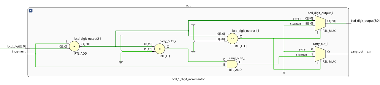
Testbench for the 1-digit BCD incrementor.
`timescale 1ns / 1ps
`define BCD_BITS 4


// Testbench
module bcd_1_digit_incrementor_testbench;
    logic [`BCD_BITS -1 : 0] a;
    logic increment;
    logic [`BCD_BITS -1 : 0] b;
    logic co; // carry out


    // Instantiate design under test
    bcd_1_digit_incrementor uut(
        .bcd_digit(a),
        .increment(increment),
        .bcd_digit_output(b) ,
        .carry_out(co) );

    initial begin
        // Dump waves
        $dumpfile("dump.vcd");
        $dumpvars(1);

        a = 4'd0;  increment = 1'b0; #10;
        a = 4'd1;  increment = 1'b0; #10;
        a = 4'd2;  increment = 1'b0; #10;
        a = 4'd3;  increment = 1'b0; #10;
        a = 4'd4;  increment = 1'b0; #10;
        a = 4'd5;  increment = 1'b0; #10;
        a = 4'd6;  increment = 1'b0; #10;
        a = 4'd7;  increment = 1'b0; #10;
        a = 4'd8;  increment = 1'b0; #10;
        a = 4'd9;  increment = 1'b0; #10;
        a = 4'd10; increment = 1'b0; #10;
        a = 4'd11; increment = 1'b0; #10;
        a = 4'd0;  increment = 1'b1; #10;
        a = 4'd1;  increment = 1'b1; #10;
        a = 4'd2;  increment = 1'b1; #10;
        a = 4'd3;  increment = 1'b1; #10;
        a = 4'd4;  increment = 1'b1; #10;
        a = 4'd5;  increment = 1'b1; #10;
        a = 4'd6;  increment = 1'b1; #10;
        a = 4'd7;  increment = 1'b1; #10;
        a = 4'd8;  increment = 1'b1; #10;
        a = 4'd9;  increment = 1'b1; #10;
        a = 4'd10; increment = 1'b1; #10;
        a = 4'd11; increment = 1'b1; #10;
        $stop;
    end

    task display;
        #1 $display("bcd_digit:%0d, bcd_digit_output:%0d, increment:%0d, carry_out:%0d",
            a, b, increment, co );
    endtask

endmodule
Waveform of the simulation
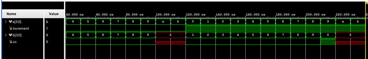
Carry-out is high only when incrementing the 9 decimal digit.
Staged 4-digit BCD incrementor from staged N-digit BCD incrementor.
We are going to design a 4-digit BCD incrementor in stages using four 1-digit BCD incrementor modules. By means of a for loop we will create a BCD incrementor of N-digits in stages.
Each increment signal input of each module is connected to the carry signal of the previous module except for the first 1-digit BCD incrementor which has its increment signal set high.
An overflow signal will indicate that the last stage produced a new carry-out.
A possible SystemVerilog implementation for the staged 4-digit BCD incrementor:
`timescale 1ns / 1ps
`define BCD_BITS 4
// BCD n-digit staged incrementor
// N: number of digits
// bcd_digits input N 4-bit BCD digits packed
// MSB corresponds to MSB of the most significant BCD digit
// bcd_digits_output the incremented by one value
// If the result exceeds the capacity of the number format overflow is set to high
module bcd_n_digit_incrementor #(parameter N=4) (
    input logic  [N * `BCD_BITS - 1 : 0] bcd_digits,
    output logic [N * `BCD_BITS - 1 : 0] bcd_digits_output,
    output logic overflow);

    logic  [N-1 : 0] stage_carry_out; // connects carry out with the increment of the next bcd 1-bit incrementor

    // first digit is always incremented
    bcd_1_digit_incrementor incrementdigitN(.bcd_digit(bcd_digits[`BCD_BITS-1:0]),
        .increment(1'b1),
        .bcd_digit_output(bcd_digits_output[`BCD_BITS-1:0]) ,
        .carry_out(stage_carry_out[0]));

    // generate and connect the next N-1 incrementors
    generate
        genvar  stage ;
        for (stage =1; stage < N ; ++stage)
        begin
            bcd_1_digit_incrementor incrementdigitN(
                .bcd_digit(bcd_digits[stage * `BCD_BITS + (`BCD_BITS-1) : stage * `BCD_BITS]), // next input digit
                .increment(stage_carry_out[stage-1]), // connect increment with carry out from previous stage
                .bcd_digit_output(bcd_digits_output[ stage * `BCD_BITS + 3: stage * `BCD_BITS]) ,
                .carry_out(stage_carry_out[stage]));
        end
    endgenerate
    assign overflow = stage_carry_out[N-1]; // connect overflow with the last stage carry out

endmodule
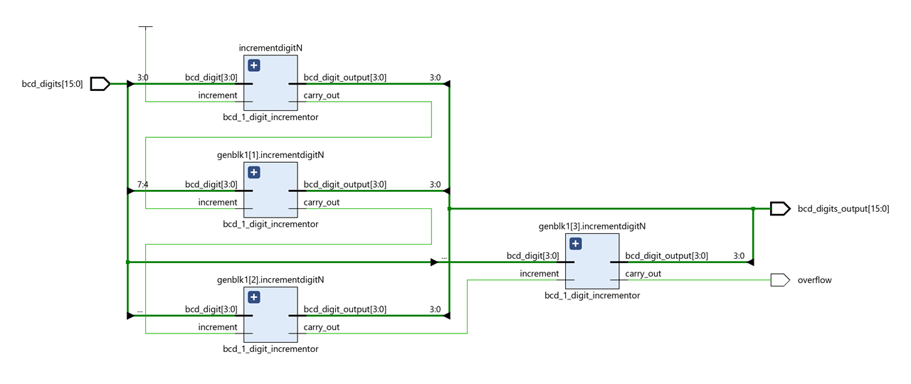
Schematic of the Vivado elaborated design:
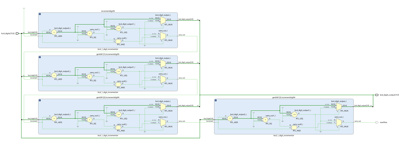
Schematic with the four stages expanded:
Testbench for the 4-digit BCD incrementor.
`timescale 1ns / 1ps
`define BCD_BITS 4
module bcd_4_digit_incrementor_testbench;
    localparam N = 4;
    logic [N * `BCD_BITS - 1: 0] a;
    logic [N * `BCD_BITS - 1: 0] b;
    logic overflow;

    localparam WIDTH = `BCD_BITS * N;

    // Instantiate design under test
    bcd_n_digit_incrementor #(.N(N)) uut( .bcd_digits(a), .bcd_digits_output(b), .overflow(overflow) );

    initial begin
        // Dump waves
        $dumpfile("dump.vcd");
        $dumpvars(1);

        a = 16'h0000; #10;
        a = 16'h0009; #10;
        a = 16'h0999; #10;
        a = 16'h9999; #10;

        a = 16'h1111; #10;
        a = 16'h0111; #10;
        $stop;
    end

    task display;
        #1 $display("bcd_digit:%0d, bcd_digit_output:%0d", a, b );
    endtask

endmodule
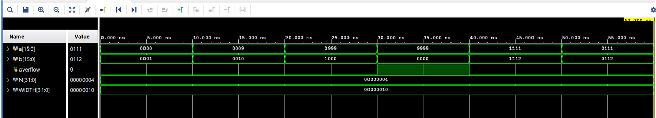
Scope view of the simulation
Conclusion
We have reviewed another format of number representation, the binary coded decimal format, and have designed a simple incrementor for a BCD digit. We have then extended the design in SystemVerilog by building an N-digit staged incrementor.
SystemVerilog Study Notes Chapters
- Gate-Level Combinational Circuit
- RTL Combinational Circuit Operators
- RTL Combinational Circuit - Concurrent and Control Constructs
- Hex-Digit to Seven-Segment LED Decoder RTL Combinational Circuit
- Barrel Shifter RTL Combinational Circuit
- Simplified Floating Point Arithmetic. RTL Combinational Circuit
- BCD Number Format. RTL Combinational Circuit
- DDFS. Direct Digital Frequency Synthesis for Sound
- FPGA ADSR envelope generator for sound synthesis
- AMD Xilinx 7 series FPGAs XADC
- Building FPGA-Based Music Instrument Synthesis: A Simple Test Bench Solution
