


We continue with combinational circuit design exercises in SystemVerilog. This time we are going to do exercises on number representation formats using a simplified floating point format.
Table of Contents
SystemVerilog Study Notes Chapters
- Gate-Level Combinational Circuit
- RTL Combinational Circuit Operators
- RTL Combinational Circuit - Concurrent and Control Constructs
- Hex-Digit to Seven-Segment LED Decoder RTL Combinational Circuit
- Barrel Shifter RTL Combinational Circuit
- Simplified Floating Point Arithmetic. RTL Combinational Circuit
- BCD Number Format. RTL Combinational Circuit
- DDFS. Direct Digital Frequency Synthesis for Sound
- FPGA ADSR envelope generator for sound synthesis
- AMD Xilinx 7 series FPGAs XADC
- Building FPGA-Based Music Instrument Synthesis: A Simple Test Bench Solution
Floating point arithmetic
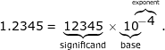
Floating-point arithmetic (FP) is arithmetic using formulaic representation of real numbers as an approximation to support a trade-off between range and precision. Floating point is another format to represent a number. With the same number of bits, the range in floating-point format is much larger than in signed integer format. In general, a floating-point number is represented approximately with a fixed number of significant digits (the significand) and scaled using an exponent in some fixed base; the base for the scaling is normally two, ten, or sixteen. A number that can be represented exactly is of the following form:
 where significand is an integer, base is an integer greater than or equal to two, and exponent is also an integer.
For example:
SystemVerilog has a built-in floating point data type, it is too complex to be synthesized automatically.
Simplified 13-bit format
For these exercises we will use a simplified 13-bit format, ignoring the round-off error.
The representation consists in
- 1-bit sign, s: which indicates the sign of the number (1'b1 for negative)
- 4-bit exponent field, e: which represents the exponent
- 8-bit significant field, f: which represents the significand or the fraction
In this format the value of a floating point number is
(-1)^s * .f * 2^e
The .f*2^e is the magnitude of the number.
(-1)^s is a formal way to state that s equal 1 implies a negative number. Sign bit is separated from the rest of the number.
When the MSB of the significand field is 1 it is in Normalized representation.
The smallest normalized nonzero magnitude in this number format representation is
0.1000_0000 * 2^0000
We also make the following assumptions:
- Both exponent and significand fields are in unsigned format
- The representation has to be either normalized or zero, if the magnitude of the computation result is smaller than the smallest normalized nonzero magnitude it must be converted to zero.
A floating-point number consists of two fixed-point components, whose range depends exclusively on the number of bits or digits in their representation. The floating-point range linearly depends on the significand range and exponentially on the range of exponent component, which attaches outstandingly wider range to the number.
Under the above assumptions, the largest and smallest nonzero magnitudes for our simplified 13-bit format are 0.1111_1111 * 2 ^ 1111 and 0.1000_0000 * 2 ^ 0000. Between 0.1 and 8,355.84
Simplified floating point adder
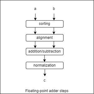
We are going to design a floating point adder that follows the same steps as when we do the addition manually when working with scientific notation.
The computation is done in several steps as indicated in the diagram:
| sort | align | add/sub | normalize | ||
| eg. 1 |
+0.54e3 |
-0.87e4 |
-0.87e4 |
-0.87e4 |
-0.87e4 |
| eg. 2 |
+0.54e3 |
-0.55e3 |
-0.55e3 |
-0.55e3 |
-0.55e3 |
| eg. 3 |
+0.54e0 |
-0.55e0 |
-0.55e0 |
-0.55e0 |
-0.55e0 |
| eg. 4 |
+0.56e3 |
+0.56e3 |
+0.56e3 |
+0.56e3 |
+0.56e3 |
- Sorting: puts the number with the larger magnitude on the top and the number with the smaller magnitude on the bottom. The results are big_number and small_number.
- Alignment: aligns the two numbers so that they have the same exponent. Adjust the exponent of the small_number to much the exponent of the big number. The significand of the small_number has to shift to the right according the difference in exponents.
- Addition/subtraction: adds or substracts the significands of the two aligned numbers.
- Normalization: adjusts the result to normalized format if
- after subtraction the result contains leading zeros
- or after subtraction the result is too small to be normalized, so needs to be converted to zero
- or after addition the result generates a carry-out bit
We will ignore rounding, during the alignment and normalization the lower bits of the significand will be discarded when shifted out.
Floating point packed struct
In SystemVerilog we can create structured data types which we use to group a number of related variables together. We will create a packed structure to group the data that represents a 13-bit floating point number of the format that we have previously defined.
package FloatingPointPkg;

// 13-bit floating point
// 1-bit sign, s: which indicates the sign of the number (1'b1 for negative)
// 4-bit exponent field, e: which represents the exponent
// 8-bit significant field, f: which represents the significand or the fraction
typedef struct packed {
    logic sign;
    logic [3:0] exp;
    logic [7:0] frac;
} fp_t;

endpackage: FloatingPointPkg
We will define a new type for the 13-bit floating point struct type
- 1-bit sign, sign: which indicates the sign of the number (1'b1 for negative)
- 4-bit exponent field, exp: which represents the exponent
- 8-bit significant field, frac: which represents the significand or the fraction
We can define all your types inside a package and simply import them wherever we want in our code. We will save the code with the new data type as a new file: "fp_types.sv" so that all modules that use it can import it.
package FloatingPointPkg;

  typedef struct packed {
     logic sign;
     logic [3:0] exp;
     logic [7:0] frac;
  } fp_t;

endpackage:FloatingPointPkg
To import:
import FloatingPointPkg::fp_t;
Floating point sorter module
We design the adder in stages, the first stage rearranges the numbers from highest magnitude to lowest without taking into account the sign, as when we place one above, the largest, and one below, smallest when we are going to subtract them.
The sorter module assigns the number with the larger magnitude to big_number output // and assignd the number with the smaller magnitude to small_number output
One possible implementation in SystemVerilog. Note that we use the structure we have created to represent floating point numbers for code clarity.
// Assigns the number with the larger magnitude to big_number output
// and assignd the number with the smaller magnitude  to small_number output
module fp_sorter(
    input fp_t a,
    input fp_t b,
    output fp_t big_number,
    output fp_t small_number);

    assign big_number = ({a.exp, a.frac} >= {b.exp, b.frac})? a: b;
    assign small_number = ({a.exp, a.frac} < {b.exp, b.frac})? a: b;
endmodule
We need to import our floating point data type .
import FloatingPointPkg::fp_t;
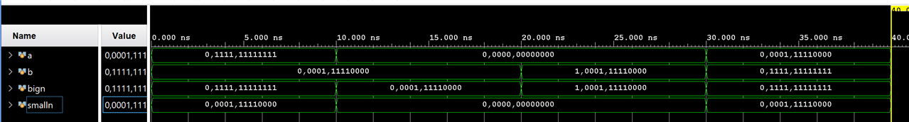
A possible testbench
module fp_sorter_testbench;
    fp_t a;
    fp_t b;
    fp_t bign;
    fp_t smalln;

    fp_sorter uut(.a(a), .b(b), .big_number(bign), .small_number(smalln));

    initial
    begin
        a ='{1'b0, 4'b1111, 8'b1111_1111};   b ='{1'b0, 4'b0001, 8'b1111_0000}; #10;
        a ='{1'b0, 4'b0000, 8'b0000_0000};   b ='{1'b0, 4'b0001, 8'b1111_0000}; #10;
        a ='{1'b0, 4'b0000, 8'b0000_0000};   b ='{1'b1, 4'b0001, 8'b1111_0000}; #10;
        a ='{1'b0, 4'b0001, 8'b1111_0000};   b ='{1'b0, 4'b1111, 8'b1111_1111}; #10;
        $stop;
    end

endmodule
Simulation
The new sorter module returns the largest and smallest number in magnitude regardless of sign.
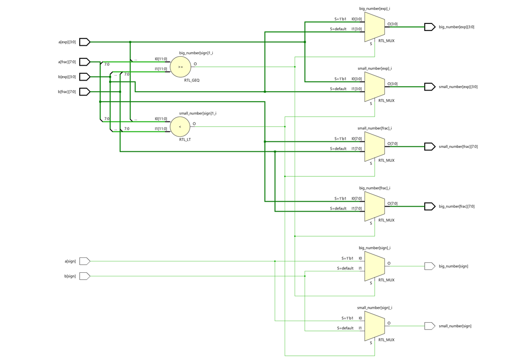
Schematic
Two comparators compare the fractional parts and exponents of both numbers. Based on the output signals of the two comparators, four 2-to-1 multiplexers route the fractional and exponent part signals of the two numbers to the outputs representing the largest and smallest number in our number sorter.
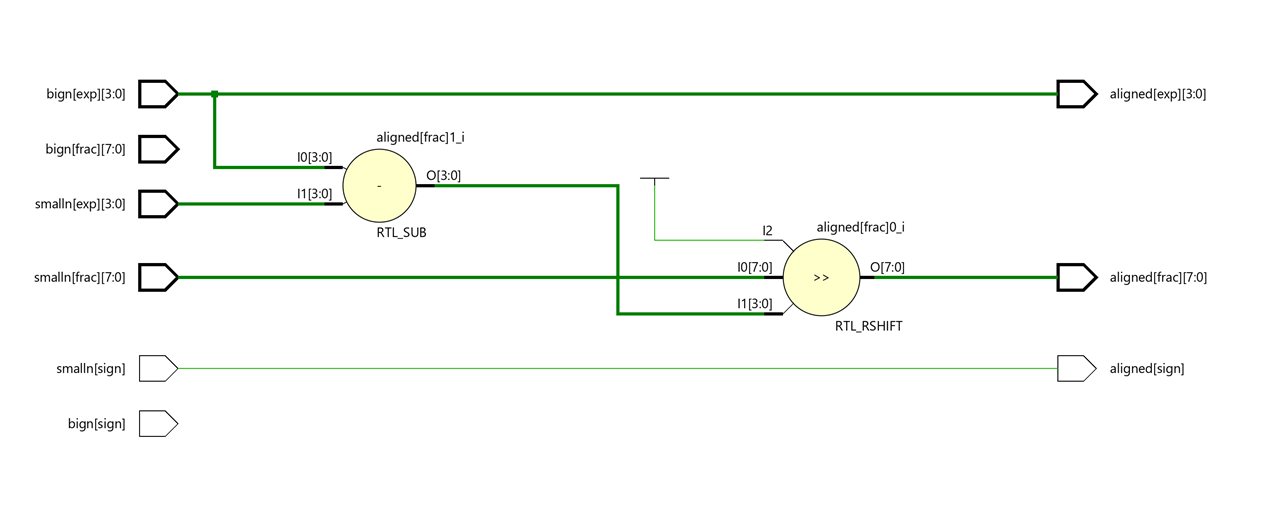
Alignment module
The alignment module aligns the two numbers so that they have the same exponent. It will adjust the exponent of the small_number to much the exponent of the big number. The significand of the small_number has to shift to the right according the difference in exponents.
`timescale 1ns / 1ps

import FloatingPointPkg::fp_t;

module fp_aligment(
    input fp_t bign,
    input fp_t smalln,
    output fp_t aligned );

    logic [3:0] exp_diff;
    always_comb
    begin
        exp_diff = bign.exp - smalln.exp;
        aligned.frac = smalln.frac >> exp_diff;
        aligned.exp = bign.exp;
        aligned.sign = smalln.sign;
    end
endmodule
Simulation
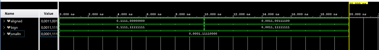
Schematic
The difference in exponents is passed to a right shifter that shifts the significand of the small_number. The exponent of the aligned result is set to the value of the exponent of the big number.
Add/substract module
This module adds or substracts the significands of two aligned numbers.
`timescale 1ns / 10ps

import FloatingPointPkg::fp_t;

// This module adds or substracts the significands of two aligned numbers, same exponent
// assumes the number are ordered big then small
module fp_sum_significands (
    input fp_t bign,
    input fp_t smalln,
    output logic [8:0] sum);

    assign sum = (bign.sign == smalln.sign) ?
     {1'b0, bign.frac} + {1'b0, smalln.frac}
     : {1'b0, bign.frac} - {1'b0, smalln.frac};

endmodule
Testbench
module fp_sum_significands_testbench;

    fp_t bign;
    fp_t smalln;
    logic [8:0] sum;

    fp_sum_significands uut(.sum(sum), .bign(bign), .smalln(smalln));

    initial
    begin
        bign ='{1'b0, 4'b0011, 8'b1111_1111};   smalln ='{1'b0, 4'b0011, 8'b1111_0000}; #10;
        bign ='{1'b1, 4'b0011, 8'b1111_1111};   smalln ='{1'b1, 4'b0011, 8'b0011_0000}; #10;
        bign ='{1'b1, 4'b0011, 8'b1111_1111};   smalln ='{1'b0, 4'b0011, 8'b0011_0000}; #10;
        bign ='{0'b1, 4'b0011, 8'b1111_1111};   smalln ='{1'b1, 4'b0011, 8'b0011_0000}; #10;
        $stop;
    end

endmodule
Simulation

The 2-to-1 multiplexer selects the output based on the sign signal of both numbers, if both signs are equal then it routes the addition result, if they are different then it routes the subtraction result.

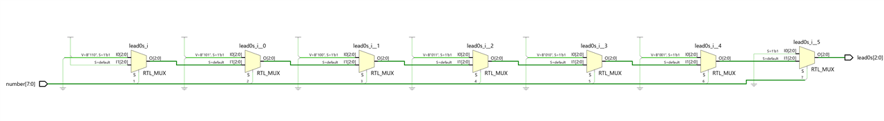
Leading 0s counter module
This module counts the number of leading zeros. It is like a priority encoder. It outputs the number of leading zeros in an 8-bit number, assumes that the are at least one high bit (value 1'b1) in case the are no bit in high it returns the higher count, 7.
This won't affect the next stage because the result will be used to shift the number to the left by the number of leading zeros. In the event that all bits are low to zero, the value it returns is irrelevant.
`timescale 1ns / 1ps

// outputs the number of leading zeros in an 8-bit number
// assumes that the are at least one high bit (value 1'b1)
// in case the are no bit in high it returns the higher count, 7
module fp_leading_zeros(
    input logic [7:0] number,
    output logic [2:0] lead0s
);

    always_comb
    begin
        if(number[7])
            begin
                lead0s = 3'o0;
            end
        else if (number[6])
            begin
                lead0s = 3'o1;
            end
        else if (number[5])
            begin
                lead0s = 3'o2;
            end
        else if (number[4])
            begin
                lead0s = 3'o3;
            end
        else if (number[3])
            begin
                lead0s = 3'o4;
            end
        else if (number[2])
            begin
                lead0s = 3'o5;
            end
        else if (number[1])
            begin
                lead0s = 3'o6;
            end
        else
            begin
                lead0s = 3'o7;
            end
    end
endmodule
Test-bench
module fp_leading_zeros_testbench;

    logic [7:0] number;
    logic [2:0] lead0s;

    fp_leading_zeros uut(.*);

    initial
    begin
        number = 8'b1111_1111; #10;
        number = 8'b0111_1111; #10;
        number = 8'b0011_1111; #10;
        number = 8'b0001_1111; #10;
        number = 8'b0000_1111; #10;
        number = 8'b0000_0111; #10;
        number = 8'b0000_0011; #10;
        number = 8'b0000_0001; #10;
        number = 8'b0000_0000; #10;
        $stop;
    end

endmodule
Simulation

Schematics
Like a priority encoder the priority network is implemented by a sequence of 2-to-1 multiplexers.
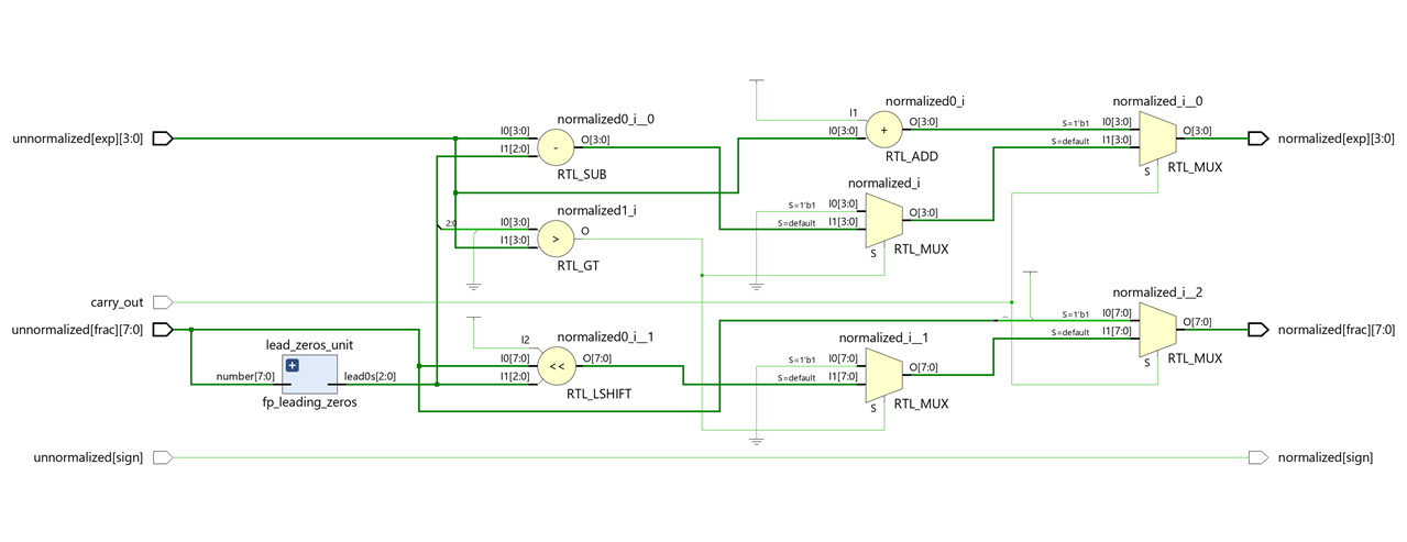
Normalization module
The Normalization module adjusts the result to normalized format if after subtraction the result contains leading zeros or after subtraction the result is too small to be normalized, so needs to be converted to zero or after addition the result generates a carry-out bit
A possible SystemVerilog implementation.
First shifts significand according leading 0s
// normalizes an unnnormalized floating point with carry out signal
module fp_normalize(
    input logic carry_out,
    input fp_t unnormalized,
    output fp_t normalized  );

    logic [2:0] lead_zeros;
    // leading zeros not incluiding the carry out
    fp_leading_zeros lead_zeros_unit(.number(unnormalized.frac),.lead0s(lead_zeros));

    always_comb
    begin
        if(carry_out) // with carry out, shift frac to the right
            begin
                normalized.exp = unnormalized.exp + 1;
                normalized.frac = {1'b1, unnormalized.frac[7:1]};
            end else if(lead_zeros > unnormalized.exp)
            begin
                normalized.exp = 0; // set to zero
                normalized.frac = 0;
            end else
            begin
                normalized.exp = unnormalized.exp - lead_zeros;
                normalized.frac = unnormalized.frac << lead_zeros; // shift significand accoding to leading 0
            end
        normalized.sign = unnormalized.sign;
    end
endmodule
Testbench
module fp_normalize_testbench;

    logic carry_out;
    fp_t unnormalized;
    fp_t normalized;


    fp_normalize uut(.*);

    initial
    begin
           carry_out = 1; unnormalized='{1'b1, 4'b0011, 8'b0000_1000}; #10;
           carry_out = 1; unnormalized='{1'b1, 4'b0011, 8'b1000_1000}; #10;
           carry_out = 0; unnormalized='{1'b1, 4'b0111, 8'b0000_1000}; #10;
           carry_out = 0; unnormalized='{1'b0, 4'b1011, 8'b1000_1000}; #10;
        $stop;
    end

endmodule
Simulation

Putting all together: Top Floating point Adder module
Finally we instantiate and connect the modules that we have designed previously:
 // circuit for reordering the inputs
 fp_sorter sort(.a(a), .b(b), .big_number(bign), .small_number(smalln));

 // circuit for aligning the smallest number
 fp_aligment align(.aligned(small_aligned), .bign(bign), .smalln(smalln));

 // circuit for add/substract the significands sum MSB 9th bit is carryout
 fp_sum_significands sum_significands(.sum(sum), .bign(bign), .smalln(small_aligned));

 // circuit for normalizing the output
 fp_normalize normalize(.carry_out(sum[8]), .unnormalized(unnormalized), .normalized(result));

 // connect addition/substraction result with the normalizer
 assign unnormalized = '{bign.sign, bign.exp, sum[7:0]};
SystemVerilog Code
`timescale 1ns / 10ps

import FloatingPointPkg::fp_t;

// binary floating point adder
module fp_adder (
    input fp_t a,
    input fp_t b,
    output fp_t result
);
    fp_t bign;  // big operand in absolute magnitude after sorting
    fp_t smalln; // small operand in absolute magnitude after sorting
    fp_t small_aligned; // small operand aligned whith the big one, same exponents
    logic [8:0] sum;  // sum of the two aligned significands with carry out
    fp_t unnormalized; // result before normalization

    // circuit for reordering the inputs
    fp_sorter sort(.a(a), .b(b), .big_number(bign), .small_number(smalln));
    // circuit for aligning the smallest number
    fp_aligment align(.aligned(small_aligned), .bign(bign), .smalln(smalln));
    // circuit for add/substract the significands
    fp_sum_significands sum_significands(.sum(sum), .bign(bign), .smalln(small_aligned));
    // circuit for normalizing the output
    fp_normalize normalize(.carry_out(sum[8]), .unnormalized(unnormalized), .normalized(result));

    // connect addition/substraction result with the normalizer
    assign unnormalized = '{bign.sign, bign.exp, sum[7:0]};

endmodule
Test bench
module fp_adder_testbench;
    fp_t a;
    fp_t b;
    fp_t c;

     fp_adder uut(.a(a), .b(b), .result(c));


    initial
    begin
        a ='{1'b0, 4'b0001, 8'b1000_0000};   b ='{1'b0, 4'b0001, 8'b1000_0000}; #10;
        a ='{1'b0, 4'b0111, 8'b1000_0000};   b ='{1'b0, 4'b0001, 8'b1000_0000}; #10;
        a ='{1'b0, 4'b0011, 8'b1010_0000};   b ='{1'b0, 4'b0010, 8'b1001_0000}; #10; //  0.160 * 2 ^ 3 + 0.144 * 2 ^ 2 = 1.28 + 0.576 = 1,856
                                                                                     // 0,0011,11101000 = 0.232 * 2 ^ 3 =  1.856
        a ='{1'b0, 4'b0000, 8'b1000_0000};   b ='{1'b0, 4'b0001, 8'b1000_0000}; #10;
        a ='{1'b0, 4'b0000, 8'b1000_0000};   b ='{1'b1, 4'b0001, 8'b1111_0000}; #10;
        a ='{1'b0, 4'b0001, 8'b1111_0000};   b ='{1'b0, 4'b0011, 8'b1111_1111}; #10;
        $stop;
    end

endmodule
Simulation

Schematics
In the schematic we can see the four main blocks of our adder: the Classification circuit, the Alignment circuit, the Addition/Subtraction circuit and the Normalization circuit, all of them interconnected.
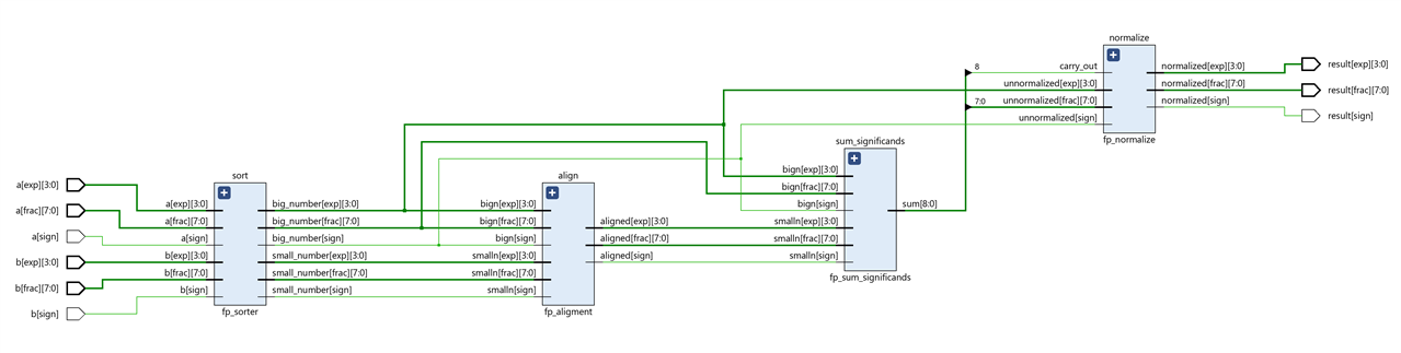
Expanded view

SystemVerilog Study Notes Chapters
- Gate-Level Combinational Circuit
- RTL Combinational Circuit Operators
- RTL Combinational Circuit - Concurrent and Control Constructs
- Hex-Digit to Seven-Segment LED Decoder RTL Combinational Circuit
- Barrel Shifter RTL Combinational Circuit
- Simplified Floating Point Arithmetic. RTL Combinational Circuit
- BCD Number Format. RTL Combinational Circuit
- DDFS. Direct Digital Frequency Synthesis for Sound
- FPGA ADSR envelope generator for sound synthesis
- AMD Xilinx 7 series FPGAs XADC
- Building FPGA-Based Music Instrument Synthesis: A Simple Test Bench Solution
