Take the Poll | Join our Discussion
sponsored by

The “Eyes and Ears” of a Device
Sensors are critical components in many devices. Sensors are the only way a device can make observations about itself and the environment. Micro-Electronic-Mechanical-Systems (MEMS) sensors are tiny integrated devices that combine mechanical and electrical components in a single package. They detect physical and mechanical changes, allowing the device to make any necessary adjustments to its operation. A variety of MEMS sensors are available, including accelerometers, gyroscopes, magnetometers, temperature, and pressure sensors. This article focuses on how MEMS sensors achieve accuracy in a few example precision applications.
The Need for Accuracy
Sensor accuracy describes how closely the sensor’s output value represents the actual measurement being monitored, while considering all possible sources of error relevant to the application. Several factors can affect accuracy; noise in the measurement environment, stability over time, ambient temperatures, as well as the sensor’s tolerance to these factors. The one of the goal’s of sensor design is to filter out as much noise as possible. The tolerance and stability of the sensor are a product of calibration and testing, accompanied by the relevant algorithms embedded within the sensor.
Precise and accurate measurements are essential in most applications. One such example is condition monitoring of a motor through vibration measurement. This application requires high accuracy in measuring vibration and stability over time, as well as temperature, in a harsh factory environment. A more accurate measurement offers better knowledge of the motor's lifespan, assists in predictive maintenance, and generates insights into working motor maintenance. Predictive maintenance reduces downtime, increases efficiency, and shortens costly labor-intensive operations. Precision and accuracy is also essential for devices in industries such as health and fitness, automated vehicles, IoT, consumer appliances and more.
How do you Design an Accurate Sensor?
MEMS sensors employ different techniques and technologies in order to increase stability and accuracy. As technology advances, newer generations of MEMS sensors become more sensitive, stable, and more precise. Current technologies include:
Accelerometers – Piezoelectric vs. Capacitive
There are two main technologies used in the design of accelerometers: piezoelectric and capacitive.
Piezoelectric – piezoelectric sensors were some of the first sensors available that offered the reliability necessary for critical applications. Piezoelectricity is a phenomenon that occurs when a quartz crystal or polycrystalline ceramic undergoes mechanical stress. What a piezoelectric crystal is at rest, the positive and negative charges within the material’s atomic structure cancel each other out. When a mechanical force presses or squeezes one side of the crystal, the structural change causes a positive or negative charge to be generated at the opposite side. These changes in voltage can be measured and used to determine movement and force. Piezoelectric sensors are widely used and are the traditional method for detecting movement in accelerometers.
Capacitive – capacitive sensors are newer technology and thus aren’t as widespread as piezoelectric sensors. The technology is advancing rapidly, and finding its way into smartphones and other mobile devices. A capacitive sensor uses a proof of mass (or seismic mass) that moves under inertial force. Several spring legs are attached to the proof of mass, with each spring leg trapped between two stationary fingers (Figure 1). When a spring leg moves with the proof of mass, one finger will measure an increase in capacitance, while the other will measure a decrease, allowing the sensor to determine both direction and amplitude of acceleration.

Figure 1: A capacitive accelerometer
Image Source: https://blog.st.com/predictive-maintenance-capacitive-mems/
Compared to a piezoelectric sensor, a capacitive sensor is more complex and more difficult to manufacture. The sample rates of capacitive MEMS are comparable to piezoelectric devices in industrial settings. For applications requiring extremely high bandwidths (10 – 20kHz), piezoelectric accelerometers are the dominant technology. Systems that benefit from accelerometers with 5 kHz sample rates can use capacitive sensors.
Capacitive sensor technology continues to improve because capacitive sensors have a variety of features that make them well suited for modern devices. Due to their architecture, they offer fast recovery time after an extreme shock. They are also very stable over time and through a wide range of temperatures, whereas a crystal might be more sensitive to changes in environment. They do not require an external analog-to-digital converter (ADC) or other signal conditioning circuit. They are also small in size, consume very little power, and cost-effective.
ST's IIS2DH capacitive MEMS was compared at 5.3 kHz sampling frequency with a piezoelectric sensor at a 6.4 kHz sampling frequency; the result yielded no discernable differences. This test showed that capacitive sensors have no downsides compared to traditional piezoelectric sensors for applications that require bandwidths supported by capacitive MEMS.
MEMS Sensors
Shop our wide variety of MEMS Sensors by ST Microelectronics.
Don't forget to take our poll.
Accelerometers – Relative Temperature vs. Absolute Temperature
Most accelerometers include a temperature sensor. In most cases, these sensors measure the voltage (Vbe) between the base and emitter of a BJT transitor, and compare it to a reference measurement set at the manufacturing line. This delta yields a relative temperature, which can then be used to calibrate the measurements from the motion sensor. To obtain temperature readings that are more precise, some accelerometers have an embedded temperature sensor that measures absolute temperature. ST's LIS2DTW12 is a low power accelerometer from its "femto" family, which sense both motion and absolute temperature in a single package. This sensor has greater precision compared to other industry-standard MEMS, thanks in part to its integrated temperature sensor.
Beyond its absolute temperature sensor functions, the LIS2DTW12 provides a 12-bit output and can sense within the -40 ºC to +85 ºC temperature range. This output has a precision of ±1.3 ºC in extreme measurements, and a typical accuracy of ±0.8 ºC between 0 ºC and 70 ºC. This compares favorably with standalone temperature sensors, which typically have an accuracy of ±0.5 ºC. The LIS2DTW12 undergoes testing at one standard ambient temperature in a single constant environment, enabling the calibration of the thermometer itself during that time to reach such precision standards.
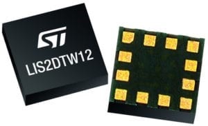
Figure 2: LIS2DTW12 MEMS Sensor
Image Source: ST Datasheet
Pressure Sensors – Piezoresistors
Pressure sensors are typically constructed using a flexible membrane with a Wheatstone Bridge on it. The membrane moves in reaction to atmospheric changes, and the positive or negative changes in the electrical resistance of the Wheatstone Bridge can be measured. ST’s LPS27HHW improves on this system with piezoresistors. Piezoresistance is the change in electrical resistivity of a solid as it changes or bends. A piezoresistive Wheatstone Bridge is one of the most sensitive ways of measuring resistance variations. The LPS27HHW can output 24-bit values and reach an Output Data Rate (ODR) of 200 Hz. Additionally, the LPS27HHW is fully water resistant and suffers no deterioration or degradation of performance over time when exposed to chlorine, bromine, salt-water, soaps, and detergents, making it useful for a variety of applications requiring resistance from the elements.
|
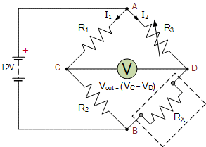
What is a Wheatstone Bridge? A Wheatstone Bridge is a simple method of measuring resistance values. It is typically drawn in a diamond shape, and consists of two series-parallel arrangements of resistances, with the unknown resistance as one of the resistors in the circuit. In the case of Figure 3, Rx is the resistance we are trying to determine.
Figure 3: Wheatstone Bridge (Source: electronics-tutorials.ws) In order to determine Rx, the circuit must be balanced, meaning Vout (between points C and D) is 0V. This is done by adjusting the values of one of the resistors. Once the circuit is balanced, Rx can be determined with this equation:  |
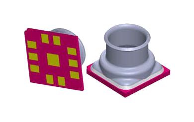
Figure 4: LPS27HHW MEMS Pressure Sensor
Image Source: ST Datasheet
ST's LPS22HH is another piezoresistive-based MEMS pressure sensor. It is sized at a compact 2.0 mm x 2.0 mm x 0.73 mm, and features exceptional shock survivability of 22,000 G with a wide absolute pressure range. The sensor operates over a -40ºC to +85 ºC temperature range with precision.
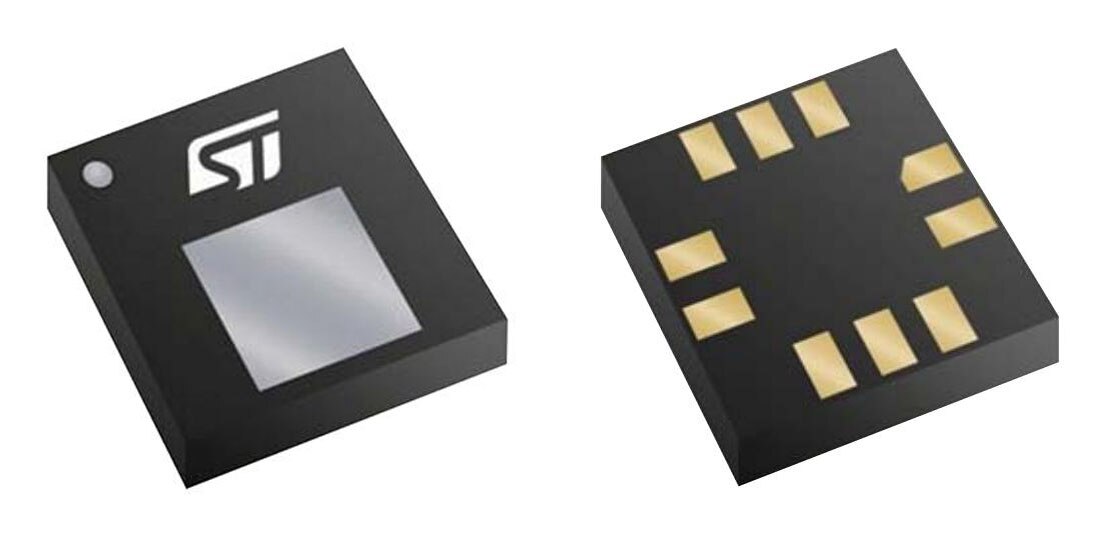
Figure 5: LPS22HH MEMS Pressure Sensor
Image Source: ST Datasheet
Applications that use MEMS Sensors
MEMS sensors are used in a variety of industries and devices, from industrial environments to consumer products such as smartphones and fitness trackers. Here we will discuss various applications, built around ST MEMS sensors.
Predictive Maintenance with Capacitive MEMS Accelerometer (IIS3DWB)
Predictive maintenance allows manufacturing facilities to identify and resolve machinery issues before they trigger catastrophic breakdowns and halt production. A superior sensing device can accurately predict machine conditions. A system with a suitable sensor, paired with appropriate processing, can detect issues such as misalignment, ball-bearing failure, and other problems. Accelerometers are a core component in such systems, and ST's IIS3DWB capacitive MEMS accelerometer is well-suited for this function. It is an ultra-low-power, high-performance, three-axis linear instrument with digital I2C/SPI serial interface standard output. It has user-selectable scales of ±2g/±4g/±8g/±16g and can measure accelerations with a bandwidth up to 6 kHz with an output data rate of 26.7 kHz. The self-test capability allows the user to check the status of the sensor. It can operate over an extended -40 °C to +105 °C temperature range. Figure 6 illustrates an example of the IIS3DWB used in this application.
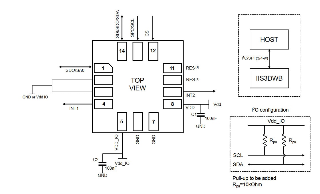
Figure 6: IIS3DWB Accelerometer Application Circuit
Image Source: ST Datasheet
Wearables with Built-in Pressure MEMS Sensor (LPS33HW)
Wearable applications, such as fitness wristwatches, need to be extremely precise and stable, because their measurements are used in observing health and wellness. The Samsung Galaxy Gear Fit2 Pro is a water-resistant fitness tracker with an ISO 22810:2010 certification for wristwatches of 5 ATMs or 50 meters (165 feet) under defined pressure, time, velocity, and temperature. ST's LPS33HW, a water-resistant MEMS pressure sensor, is a vital component of this product. It is an ultra-compact piezoresistive pressure sensor that works as a digital output barometer. The device contains an IC interface and a sensing element. The interface communicates via I2C or SPI from the device's sensing element to its application. The absolute pressure detecting sensing element is a dedicated, process-developed suspended membrane manufactured by ST. Figure 4 shows the application circuit for this sensor.
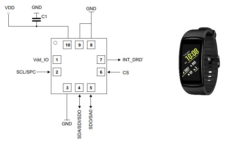
Figure 7: LPS33HW Sensor Application Circuit
Image Source: ST Datasheet
Summing Up: Accuracy in the Design of MEMS Sensors
As technology advances, the shrinking size of electronic components are enabling the next generation of devices. As the eyes and ears of the device, sensors play a crucial role. Precision and accuracy are paramount in many applications, and various techniques are utilized in the design of MEMS sensors to achieve the necessary sensitivity and stability.

