Take the Poll | Join our Discussion
sponsored by

Improving Renewable Energy
Renewable energy reduces our dependence on fossil fuels, which helps reduce our carbon footprint. Examples of renewable energy sources include wind and solar. While the technology has come a long way, renewable energy has not yet been able to replace fossil fuels and other traditional energy sources. A great deal of research and development is dedicated towards improving efficiency when generating clean power. Efficiency can be improved at various points, one of which is the power inverter. Inverters convert DC power to AC, typically utilizing power relays for grid interconnection. Relays can often be sources of inefficiency due to the generation of heat. This article discusses inverters, with a focus on power relays, and ways to improve their efficiency in renewable energy applications.
Renewable Energy and Applications
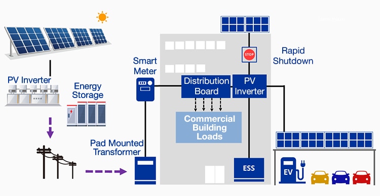
Renewable energy is energy that comes from naturally replenishable processes, such as sunlight, wind, the flow of water, and geothermal heat sources. Figure 1 depicts a block diagram of a solar power generation and management system. A photovoltaic (PV) inverter converts the DC power generated from the solar panels into AC power.

Figure 1: Solar Photovoltaic Power Generation Systems
Source: Omron
What's the difference between DC and AC power?
Direct Current (DC) flows in just one direction and at a constant magnitude. Figure 2 depicts graphs of the magnitude of DC versus Alternating Current (AC) voltage with respect to time. Because the electrons flow in only one direction with DC power, its magnitude is represented as a straight line. An example of a DC power source is a battery. A battery continuously transports electrical energy in one direction through a device until the battery energy depletes. Solar panels also produce direct current.

Figure 2: AC Power vs. DC Power
Source: ElProCus.com
An Alternating Current (AC) periodically switches its direction at 50/60 Hz, the standard powerline frequency for Europe and Asia/North America).. Because of this movement, the magnitude of Alternating Current appears as a sinusoidal wave, as shown in Figure 2. An example of AC power would be the residential electricity supply. Most electronics run on AC power, converting to DC power internally when necessary.
When it comes to sending energy through long distance transmission lines, AC power has several advantages. With AC power, voltage can be quickly stepped up or down with transformers, allowing a high voltage for transmission that can be stepped down at the end user’s point of supply. A high transmission line voltage allows high power levels to be sent with relatively small currents, leading to less power loss due to resistance in the wires.
How does an inverter work?
Most devices are designed to use AC power, therefore, the DC power from a battery or solar power generator has to be converted to AC. This is done with an inverter. An inverter quickly switches the direction of a DC input back and forth (50‐60 times per second) to convert DC power to AC power. Mechanical inverters use either an automated switching mechanism or an electric motor to flip and swap the incoming direct current by reversing the contacts. Because this output waveform might be square shaped, filters are used to shape it into a clean, repeating sine wave. Sine waves produce less harmonic distortion than square waves, reducing the risk of damage to sensitive equipment. Items such as printers, scanners, monitors, and audio amplifiers also produce less glitches and electronic noise when powered with a sine wave power source. Additionally, some devices sense the phase or the zero voltage crossing for applications such as motor control. For this purpose, the voltage from a sine wave has a much smoother rise and fall when compared with a square wave.
There are two types of inverters: true/pure sine wave (PSW) and modified/quasi sine wave (MSW) inverters. True inverters use electronic circuits and toroidal transformers to convert DC into a genuine sine wave, similar to the AC signal that is usually supplied to residences. Modified sine wave inverters are less expensive and produce an output that is more like a "rounded-off" square wave.
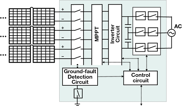
Figure 2 illustrates a PV inverter block diagram where an array of PV solar panels is connected with an MPPT (Maximum Power Point Tracking) block. The MPPT is an integrated feature in all grid-tied solar inverters that ensures solar panels are always working at their maximum efficiency, independent of the environmental conditions or the solar intensity. An MPPT is usually controlled by a microcontroller, which samples panel voltage and currents, and then adjusts the duty ratio, or impedance, that is seen by the solar cell. The DC power that is generated from the PV panels is then fed into an inverter for conversion to AC.

Figure 2: PV Inverter Block Diagram
Source: Omron
Controlling High Power Loads with Relays
High power relays are used with inverters for the switching of high power loads. Relays are switches that use an electrical signal from one circuit to control another circuit that may be operating at a different voltage, for example, using a digital logic circuit operating at 5V to control machinery running at much higher voltages. With inverters, relays perform the switching between high power loads, such as batteries or PV cells. They are also used to safely shut down power grids. Relays, however, are one of the components where power loss can occur, due to factors such as contact resistance.
What is contact resistance?
The contacts of a relay are electrically conductive pieces of metal that connect to complete a circuit, allowing current to flow. In theory, closed relay contacts are equivalent to a short circuit, meaning there is zero contact resistance; however, all relay contacts have some amount of resistance. Contact resistance is a combination of several factors: the inherent resistance of the armature, terminals, and contacts, and the boundary resistance where the two contacts meet.
The higher the contact resistance is, the more heat is generated as current flows through the contact. In addition, the voltage drop across the contact grows larger as contact resistance increases, diminishing the actual load voltage. A lower contact resistance improves efficiency and reduces heat generation, allowing a smaller heatsink to be used, which in turn, conserves space and cost.
Under certain circumstances, contact-making or breaking under load can cause an electric spark. The super high temperature of these arcs can cause damage to the contact layers, causing other contaminants or particles near the point of contact to burn or disintegrate. During severe arcing, the contacts may even weld together, leading to a short, a dangerous condition that can lead to damage to surrounding circuits.
For best performance and long lifespan, modern contact tips can either be made from silver-based alloys or specially coated. When used as contact material, silver-based alloys have low contact resistance and reduce the potential of contact arcing. The characteristics of commonly used contact materials are listed in the following table.
| Ag (fine silver) |
|
| AgCu (silver copper) |
|
| AgCdO (silver cadmium oxide) |
|
| AgW (silver tungsten) |
|
| AgNi (silver nickel) |
|
| AgPd (silver palladium) |
|
| Platinum, Gold, and Silver Alloys |
|
Omron G9KA Relays
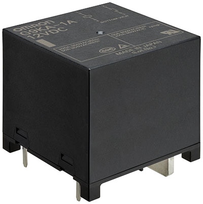
Omron G9KA series relays are AC-power, PCB relays designed for high power applications in the energy market, one example being PV inverters. They use a unique contact material that accommodates a maximum of 800VAC, with a 200A high current breaking capability, while keeping heat generation to a minimum due to a twin contact design and a low contact resistance of 0.2mΩ. Reducing contact resistance and shunting the current through two contacts can suppress heat generation up to roughly 30%, even with high loads. The low contact resistance is maintained over the lifetime of the relay. G9KA series relays are available in a compact and low-profile package of 51mm x 51mm x 42.7mm.

Figure 3: Omron G9KA
Buy Now
Figure 4 illustrates how heat generation can be reduced by using a twin contact configuration vs a single contact configuration. Instead of 200A going through a single contact, the current is dispersed through two contacts, each one carrying half the current. The equations in Figure 4 demonstrate how heat generation is halved with a twin contact configuration.
Figure 4: Comparison of Heat Generation between Single Contact and Twin Contact configurations
Source: Omron
Figure 5 depicts the results of a temperature rise simulation comparing two relays, a G9KA Series relay and a relay with higher contact resistance. The testing setup consisted of the relay and a terminal block, cooled by a fan, duct, and heat sinks. The simulation was performed at a 200A carry current. The results show that contact resistance clearly has a measurable effect in reducing heat stress.
Figure 5: Temperature rise simulation comparing contact resistance in relays
Source: Omron
Summing up: Maximizing efficiency in renewable energy
One of the biggest challenges with renewable energy is efficiency; how to make the most of the energy that is generated. Several factors can contribute to energy loss, one of which is heat generation in the power inverter. Relays play an important role in inverters; however, they can be a source of heat. To help improve efficiency in inverters, Omron has created the G9KA series of high power relays, which improve efficiency by reducing the amount of heat generated as current passes through the contacts. To this end, the G9KA series features ultra-low contact resistance and a twin contact design, both of which minimize the generation of heat in power applications.
