element14 Community
element14 Community
    Register Log In
  • Site
  • Search
  • Log In Register
  • About Us
  • Community Hub
    Community Hub
    • What's New on element14
    • Feedback and Support
    • Benefits of Membership
    • Personal Blogs
    • Members Area
    • Achievement Levels
  • Learn
    Learn
    • Ask an Expert
    • eBooks
    • element14 presents
    • Learning Center
    • Tech Spotlight
    • STEM Academy
    • Webinars, Training and Events
    • Learning Groups
  • Technologies
    Technologies
    • 3D Printing
    • FPGA
    • Industrial Automation
    • Internet of Things
    • Power & Energy
    • Sensors
    • Technology Groups
  • Challenges & Projects
    Challenges & Projects
    • Design Challenges
    • element14 presents Projects
    • Project14
    • Arduino Projects
    • Raspberry Pi Projects
    • Project Groups
  • Products
    Products
    • Arduino
    • Avnet Boards Community
    • Dev Tools
    • Manufacturers
    • Multicomp Pro
    • Product Groups
    • Raspberry Pi
    • RoadTests & Reviews
  • Store
    Store
    • Visit Your Store
    • Choose another store...
      • Europe
      •  Austria (German)
      •  Belgium (Dutch, French)
      •  Bulgaria (Bulgarian)
      •  Czech Republic (Czech)
      •  Denmark (Danish)
      •  Estonia (Estonian)
      •  Finland (Finnish)
      •  France (French)
      •  Germany (German)
      •  Hungary (Hungarian)
      •  Ireland
      •  Israel
      •  Italy (Italian)
      •  Latvia (Latvian)
      •  
      •  Lithuania (Lithuanian)
      •  Netherlands (Dutch)
      •  Norway (Norwegian)
      •  Poland (Polish)
      •  Portugal (Portuguese)
      •  Romania (Romanian)
      •  Russia (Russian)
      •  Slovakia (Slovak)
      •  Slovenia (Slovenian)
      •  Spain (Spanish)
      •  Sweden (Swedish)
      •  Switzerland(German, French)
      •  Turkey (Turkish)
      •  United Kingdom
      • Asia Pacific
      •  Australia
      •  China
      •  Hong Kong
      •  India
      •  Korea (Korean)
      •  Malaysia
      •  New Zealand
      •  Philippines
      •  Singapore
      •  Taiwan
      •  Thailand (Thai)
      • Americas
      •  Brazil (Portuguese)
      •  Canada
      •  Mexico (Spanish)
      •  United States
      Can't find the country/region you're looking for? Visit our export site or find a local distributor.
  • Translate
  • Profile
  • Settings
Enchanted Objects
  • Challenges & Projects
  • Design Challenges
  • Enchanted Objects
  • More
  • Cancel
Enchanted Objects
Blog 1958 Turntable from the Black Forest - 4: Motor control with Infineon Motor Shield and Arduino UNO
  • Blog
  • Forum
  • Documents
  • Polls
  • Files
  • Events
  • Mentions
  • Sub-Groups
  • Tags
  • More
  • Cancel
  • New
  • Share
  • More
  • Cancel
Group Actions
  • Group RSS
  • More
  • Cancel
Engagement
  • Author Author: Jan Cumps
  • Date Created: 24 Mar 2015 8:20 PM Date Created
  • Views 1312 views
  • Likes 7 likes
  • Comments 4 comments
  • motor_driver
  • infineon
  • enchanted_player
  • enchanted_objects
  • pwm
  • arduino_uno
  • arduino
Related
Recommended

1958 Turntable from the Black Forest - 4: Motor control with Infineon Motor Shield and Arduino UNO

Jan Cumps
Jan Cumps
24 Mar 2015

image


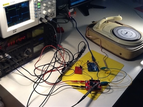
Time for the first electronics post. We're going to drive my turntable motor with the Arduino Uno and the Infineon motor shield.


image

The Infineon DC Motor Control Shield is connected to the Arduino UNO. The Arduino controls the motor power by sending PWM signals to the shield.

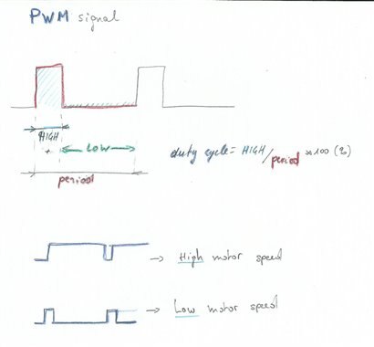
The duty cycle of the PWM defines how much power is going to the motor. I'm using that technique to speed up and slow down the motor.


The signal


The Arduino is generating the PWM signal. When you drive a motor with PWM, it's not the frequency that drives the motor speed, but the duty cycle of the signal.

image


The easiest way to get a PWM signal on an Arduino with variable duty cycle is by calling analogWrite().

There's noting wrong with that for most applications, but it's not ideal for my project.

The frequency of this standard method is somewhere between 900 and 1000 Hz. And that is in the audio range.

I risk getting my turntable's signal polluted by the PWM signal.


To mitigate that, I used a library that supports higher frequency PWM: the Timer1 lib.


The Timer1 Arduino library


This library allows me to lift the PWM frequency above the frequencies that we can hear (if you are not a bat).

I settled for 33.3 kHz (a period of 30 µs).


#include <TimerOne.h>

const byte PWMpin = 9; // PWM only supported on pin 9 or 10
const byte INH_1 = 11;
int iDC = 705; // exact speed at 10 volt

void setup(void) {
  // ...
  pinMode(PWMpin, OUTPUT);  
  pinMode(INH_1, OUTPUT);
  Timer1.initialize();
  Timer1.pwm(PWMpin, iDC, 30); // duty cycle [10 bit], period [us] <8388480
  digitalWrite(INH_1, HIGH); // enable OUT1
}


I define two pins as outputs here:

image

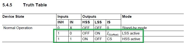
Pin 9 is connected to the half H-Bridge IN port. This is the PWM input that will control how much energy the motor shield sends to the motor.

Pin 11 connects to the half H-Bridge INH port. Driving this one low will stop the motor, whatever we do with pin 9.


Then we tell the library to generate a 33 kHz signal on pin 9, with a duty cycle of 705.

The duty cycle range goes from 0 to 1023. So you have to interpret this 705 as (705/1023)*100 = 68%.

I've chosen 705 because that gives me a correct turntable speed when I supply 10 V to the motor shield.


You don't have permission to edit metadata of this video.
Edit media
x
image
Upload Preview
image


The pictures below show the PWM signal at different duty cycles.

The signal is probed at pin 9 of the Arduino.


200511676
imageimageimage


Test Bed


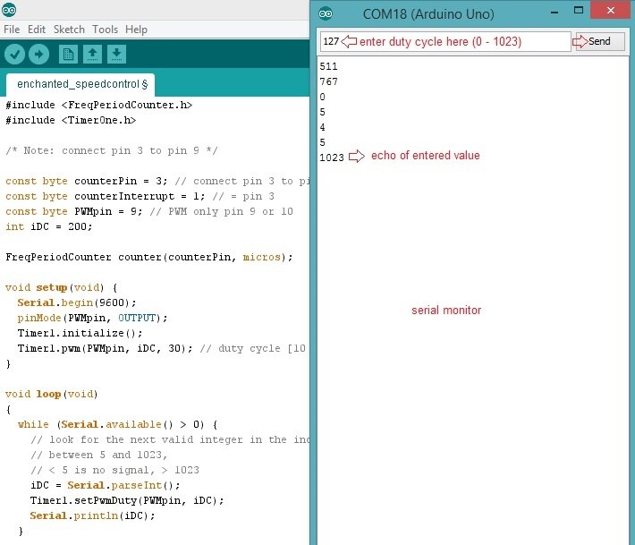
I've extended my sketch to make the duty cycle variable. You can enter a duty cycle in the Arduino IDE serial monitor, and that value is then sent to the Timer1 lib.


void setup(void) {
  Serial.begin(9600);
  // ...
  Serial.println("Ready for input...");
}

void loop(void)
{
  while (Serial.available() > 0) {
    // look for the next valid integer in the incoming serial stream,
    // between 5 and 1023,
    // < 5 is no signal, > 1023
    iDC = Serial.parseInt();
    Timer1.setPwmDuty(PWMpin, iDC);
    Serial.println(iDC);
  }
}


The setPwmDuty() immediately changes the duty cycle, and alters the motor speed.

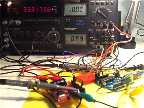
This is an ideal test bed to exercise the motor driver design.


image


The Result


With the firmware ready and everything wired up, let's have a look at some results.


imageimage

The picture below shows the input and output signal of the shield at a duty cycle of 705 (68%).

The yellow signal is probed at pin 9 of the Arduino. The blue signal is measured at out1 of the shield.

image

You can see the switching time on the capture. i've highlighted it with the two vertical cursors. I measured 4.40 µs.

You can find a more detailed review of the shield and the signals  in Vintage Turntable repair: Can I fix a Perpetuum Ebner from 1958 - part 3 - Infineon Motor Driver shield.


The Limits


The shield doesn't work from 0 to 100%. I've used the test bed to measure the working range in my circuit and with my firmware.

It's dependent on the frequency. The half H-Bridge needs time to switch on and off. So the total period of a PWM signal plays a role in the upper and lower limits.

I hit them around 10% and 86%. You can see that in the captures below.


In each of the captures, the blue signal is the output just outside the working range.

The white signal is a stored signal just within the range.


Lower limitUpper limit
imageimage


You can see that the output signal flatlines in both situations. The output under 10% is 0 V, above 86% it's the input voltage of the shield (give and take some).


Voila. The motor drive part is finished. I'm now ready to start with the speed detector.


Table of Contents
Chapter 1: Fix the turntable
1: Perpetuum Ebner Musical 1
2: A Time to Kill and a Time to Heal
3: Preparation for Motor Drive
4: Motor control with Infineon Motor Shield and Arduino UNO
5: Turntable speed sample testbed with Arduino UNO
6: Turntable Speed Sensor design
7: Control Theory - End of Chapter 1
Chapter 2: First Enchantments
8: Digital Light Organ Enchantment
9: Autonomous Servo Lift
10: SMD Time - Solder the IR Speed Sensor PCB
11: Yelp - who can Help me to Compile and Run my First SAMA5D4 C Program
12: Son et Lumiere - End of Chapter 2
Chapter 3: Taming the Board
13: Breakthrough - Run my own C++ Program on the SAMA5D4
14: Digital Light Organ Input Buffer
15: SAMA5D4 Blinky
16: Scope Creep
17: Audio Sampling with 16-bit ADC ADS8343
18: Sending Files to SAMA5D4 over USB
19: Port my Light Organ from Arduino to SAMA5D4
20: Fast Fourier Transform on the SAMA5D4 - End of Chapter 3
Epilogue: Reaching for the Clouds
21: Right-Sizing my Plans
22: My Own C++ Buffered Sampler on the SAMA5D4
Interlude
23: Building In the Motorized Light Organ
24: Up to the Clouds with Yún
25: Publish or Perish
26: Turntable Finished
Stretch & Boni
Bonus 1a: Remote Light Organ with WiFI pt. 1
Bonus 1b: Remote Light Organ with WiFI pt. 2
Grande Finale: Paho MQTT Client on the SAMA5D4
Related blog
Vintage Turntable repair: Can I fix a Perpetuum Ebner from 1958
Review 1: Atmel SMART SAMA5D4 Xplained Ultra Unboxing and First Steps
Review 2: Atmel SMART SAMA5D4 Xplained Ultra - Building the Libraries from Source
Review 3: Digital Continuous Rotation (360°) Servo Part 1
Review 4: Digital Continuous Rotation (360°) Servo Part 2
Review 5: Atmel SMART SAMA5D4 Xplained Ultra - TCP/IP running
Review 6: Atmel SMART SAMA5D4 Xplained Ultra - LINUX Distro with SSH support
poem
Enchanted Objects: Let's work together to tame the ATMEL SMART SAMA5D4 Xplained Ultra kit
17 bis: Off South...
Review 7: Atmel SMART SAMA5D4 Xplained Ultra - C++ ADC Example on Linux
Review 8: Atmel SMART SAMA5D4 Xplained Ultra - Product Review
Review 9a: Atmel SMART SAMA5D4 Xplained Ultra - Set up ADC Buffer with Hardware Trigger Part 1
Review 9b: Atmel SMART SAMA5D4 Xplained Ultra - Set up ADC Buffer with Hardware Trigger Part 2
Review 10: Atmel SMART SAMA5D4 Xplained Ultra - New Content on AT91.com
1958 Turntable from the Black Forest - Summary of the Enchanted Player Story
  • Sign in to reply

Top Comments

  • Jan Cumps
    Jan Cumps over 10 years ago +1
    I may try out this library for speed measurement:of my turntable plcLib (Arduino): Counting and Counters - Electronics and Micros
  • Jan Cumps
    Jan Cumps over 10 years ago

    I may try out this library for speed measurement:of my turntable

    plcLib (Arduino): Counting and Counters - Electronics and Micros

    • Cancel
    • Vote Up +1 Vote Down
    • Sign in to reply
    • More
    • Cancel
  • Workshopshed
    Workshopshed over 10 years ago in reply to Jan Cumps

    Ah yes, a saw tooth into the mosfet h-bridge might not work too well.

    • Cancel
    • Vote Up 0 Vote Down
    • Sign in to reply
    • More
    • Cancel
  • Jan Cumps
    Jan Cumps over 10 years ago in reply to Workshopshed

    It is an interesting idea. I see some things that may not play well though.

    The RGB shield doesn't create PWM, but sawtooth output (shabaz has put captures in RGB LED Shield from Infineon - Getting Started Guide)

    It's specialized in a constant current.

    It may not like the motor's inductive load if I drive the motor directly from it.


    However, I have a spare RGB shield left over from a previous design challenge. I may give the combination a try with another motor I have lying around here image.

    • Cancel
    • Vote Up 0 Vote Down
    • Sign in to reply
    • More
    • Cancel
  • Workshopshed
    Workshopshed over 10 years ago

    Here's a strange thought, could the RGB driver board be used to generate a PWM signal in this case?

    • Cancel
    • Vote Up 0 Vote Down
    • Sign in to reply
    • More
    • Cancel
element14 Community

element14 is the first online community specifically for engineers. Connect with your peers and get expert answers to your questions.

  • Members
  • Learn
  • Technologies
  • Challenges & Projects
  • Products
  • Store
  • About Us
  • Feedback & Support
  • FAQs
  • Terms of Use
  • Privacy Policy
  • Legal and Copyright Notices
  • Sitemap
  • Cookies

An Avnet Company © 2025 Premier Farnell Limited. All Rights Reserved.

Premier Farnell Ltd, registered in England and Wales (no 00876412), registered office: Farnell House, Forge Lane, Leeds LS12 2NE.

ICP 备案号 10220084.

Follow element14

  • X
  • Facebook
  • linkedin
  • YouTube