


The basis for my turntable enchantment is almost done. I'm very close to having a working turntable.
Let's have a look at the speed sensor circuit today. One of the very last things to complete for this basis part.
The Speed Sensor
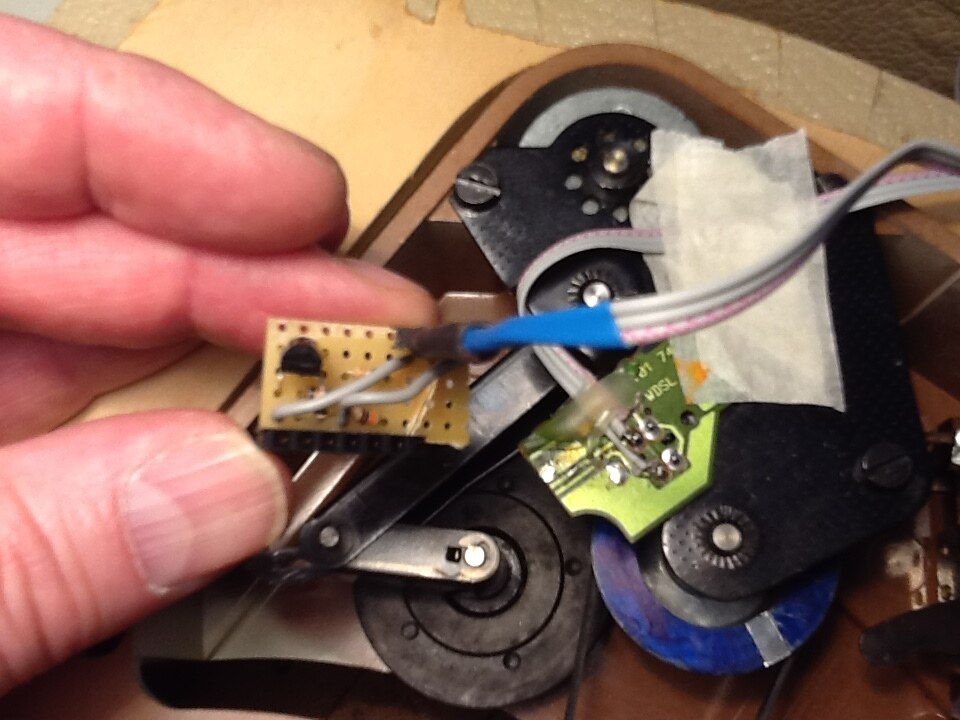
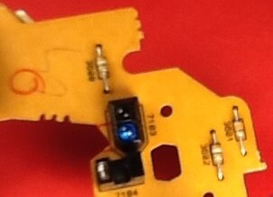
The sensor is an infrared opto-coupler. It was component of a 'for parts' video recorder.
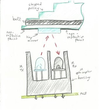
I've placed one of those under the stepped pulley of the Perpetuum-Ebner. I painted the underside of that pulley in a non-reflective color.
Then I glued a small piece of mirror (it's actually a piece of shiny foil that I removed from a toy of one of my girls) on that.
The infrared transmitter is always on.
When the mirror is above the coupler, the receiver conducts. When the mat paint is above the pair, it goes into high resistance..
The Sensor Circuit
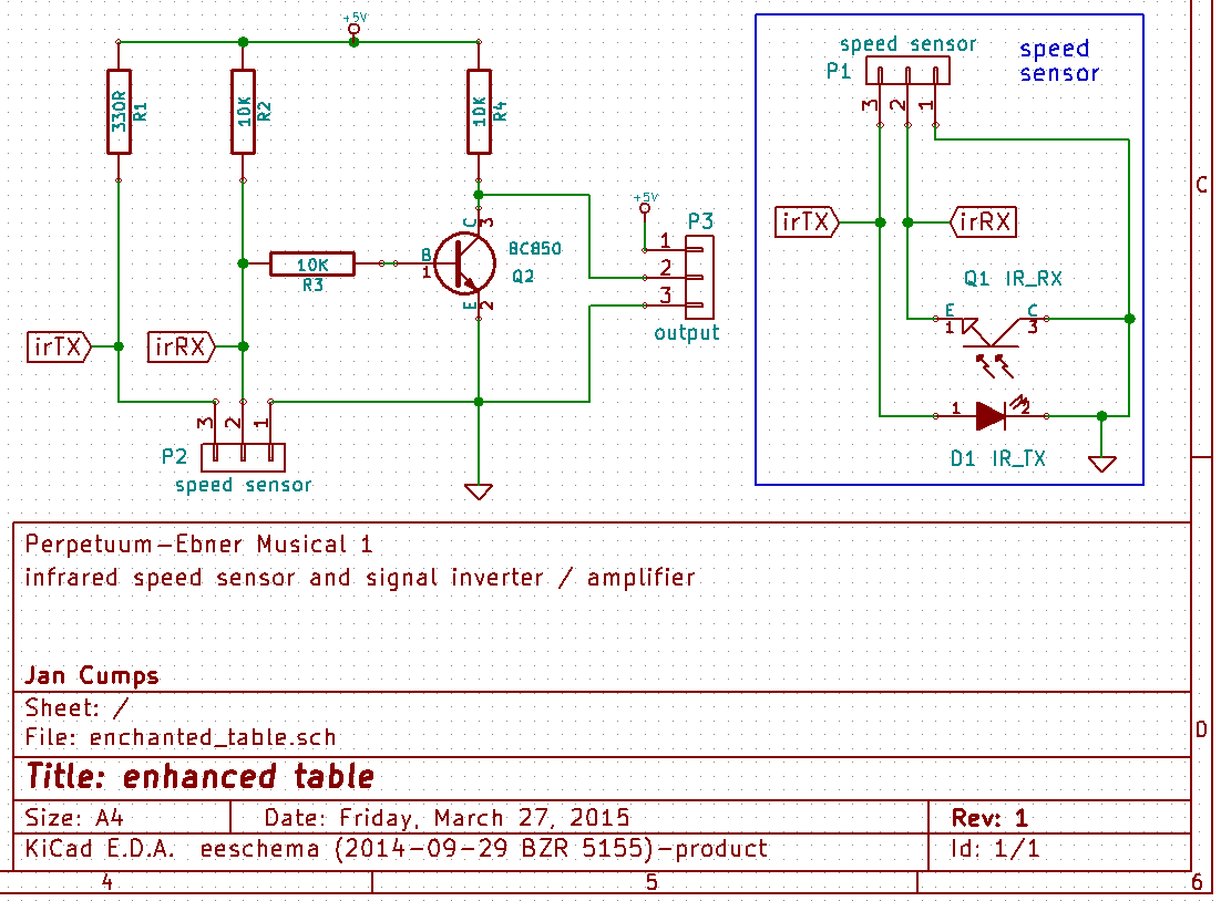
My sensor circuit has two duties. It has to power the tx, and it has to translate the state change of the receiver into a signal that we can feed into the Arduino.
Powering the IR light sender is easy. In this circuit, it's always on. We'll power it from the Arduino's 5 V.
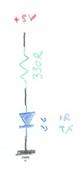
With the setup above, we'll get a constant IR beam pointing to the underside of the pulley.
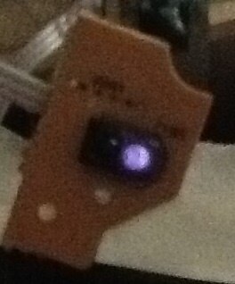
tip: you can see that an IR LED is emitting light by looking at it with a digital camera.
|
The receiver is set up as a voltage divider.
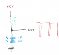
When the light is not reflected, the receiver's internal resistance is much higher than the 10K resistor in series.
The effect is that almost all of the 5 V source will be over that receiver.
So the signal is high when the mirror is not above the opto-coupler.
When the mirror is above the sender and receiver, the beam of the sender reaches the receiver. Its internal resistance is low when agitated by the beam.
In that case, the 10K series resistor is the dominant component, and most of the 5 V source will be over that resistor.
The voiltage over the receiver will be close to 0 V.
So the signal is low when the mirror is above the opto-coupler.
I have added an inverting amplifier to that output. It's just your usual high gain one-transistor setup.
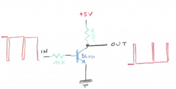
The high gain will do a few things with the signal. It removes a bit of the noise when the infrared beam bounces against the dark part of the pulley.
The paint is not evenly applied (it is actually just blue sharpie ink). The transistor is driven into full saturation when its input driven.
So the noisy high input signal becomes a clean low signal (inverting amp!) at the output.
The second achievement of the amplifier is to make the edges of the signal sharper. The high gain takes care that the transistor is quickly switched on and off.
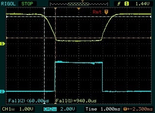
This turns the analog input signal into a nice digital one.
| output after the amplifier | zoom in of one amplified pusle |
|---|---|
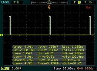 | 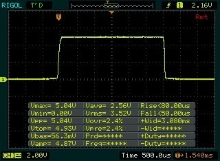 |
The Prototypes
I've made two prototypes. The first one on a breadboard, so that I could test the firmware, tweak some values and make design changes if needed.
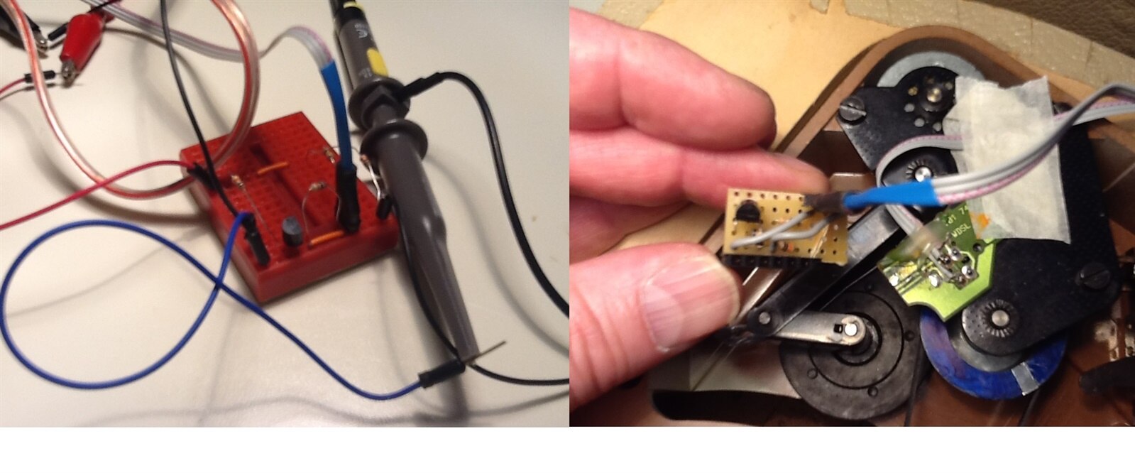
And as a temporary solution that I can build into the table, I've soldered the circuit on Veriboard.
This is really temporary. I'm making a tiny SMD print for the final sensor circuit.
The Final Sensor Board
I've made a PCB design in KiCAD. I've made a choice a while ago to never ever return to through-hole, so this is an SMD design.
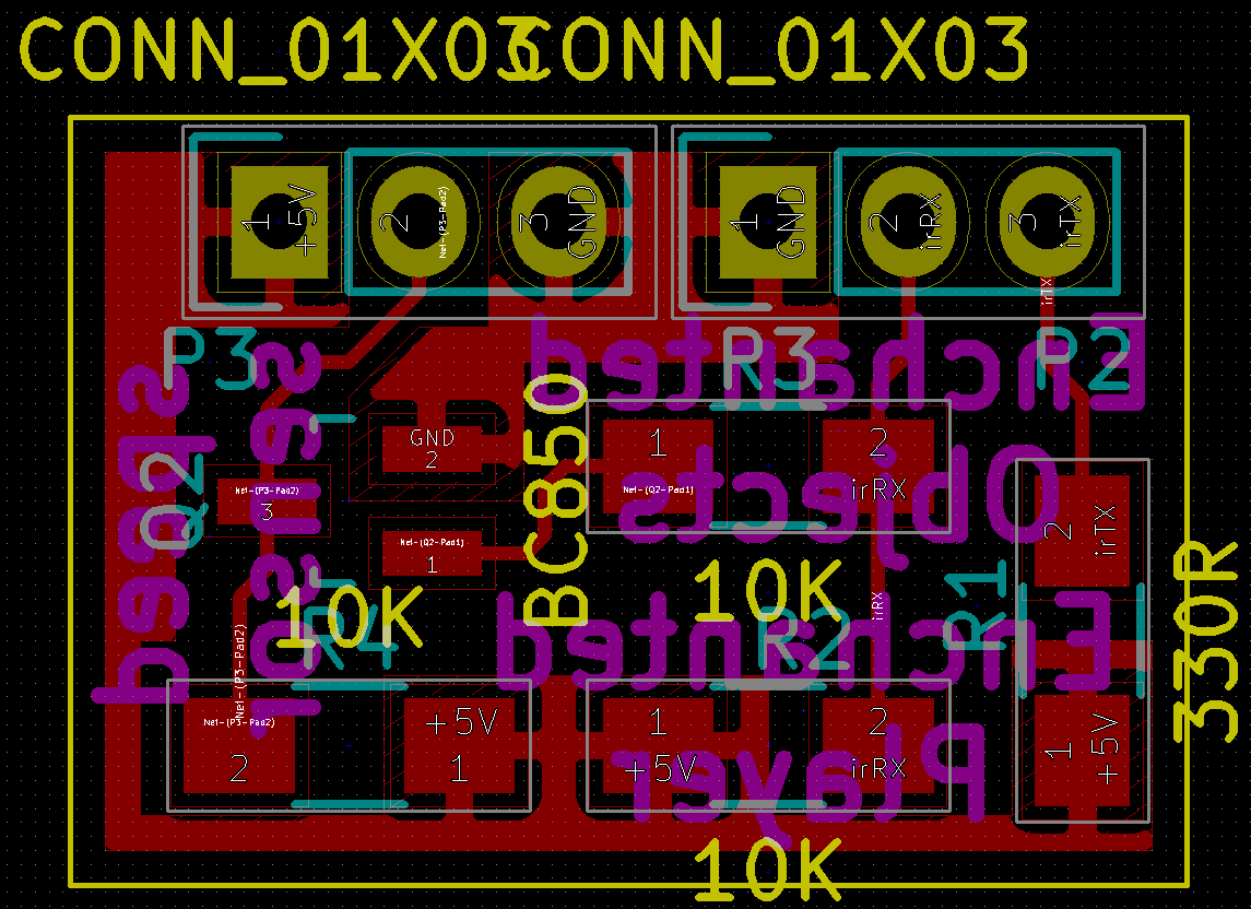
The KiCAD sources, and the fab files for OSH Park are attached. I've designed the PCB for hand soldering.
This is the schema:
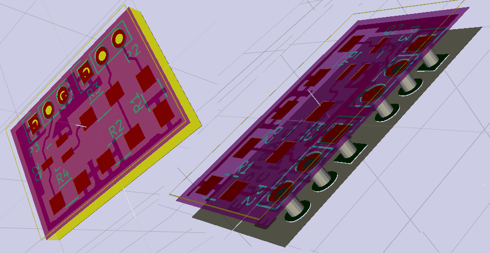
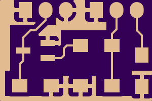
And this is the PCB layout:
I settled for a single side design. If I'd take the proper time to make a double sided design, I believe I could reduce the size to little more than what's needed for the headers.
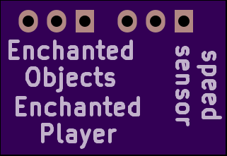
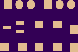
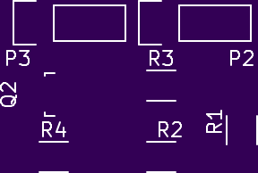
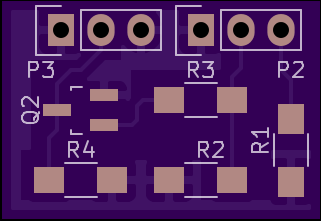
The gallery shows a few of the previews that OSH Park presents when you upload the fab files.
I like that they show all aspects of how your board will look like after production. Some errors like drilling hole mismatches show very well in their report.
I always take the time to review the OSH Park rendering before committing the funding for the PCB.
| {gallery} OSH Park PCB preview |
|---|
Preview 1:PCB back |
Preview 5: can't remember |
Preview 6: can't remember |
Preview 7: Component outline |
Preview 9: PCB front |

It will take at least 15 days for the PCB to arrive. Meanwhile the Veroboard proto will do the sensor duty.
Side story: Perpetuum Ebner
The two Steidinger brothers were born in a watchmaker family. It's only natural that their first steps in the industry were watch related. The Black Forest watch making tradition is very different from what was happening in Swiss at the time. In Swiss, they were specializing in wristwatches. There was a thriving industry then, and there is still one now. In the Black Forest, the clock industry was evolving around furniture clocks. The mechanics were only one part of the work. There was also a big woodworking guild that specialized in the typical rustique cabinets that we still link to that region. The cuckoo clock may be the best known article. The brothers were making mechanical parts for those clocks. Each on their own, in their own small start-up. In their spare time they started to experiment with early phonograph mechanisms. The early record player designs shared quite some things with clocks. The feather motor that powered so many clocks at the time was also used by the first phonograph manufactures. The Steidingers were looking for options to broaden their gamma. Business was not great in the pre-war era. If they only could find something that made more money than those clock parts, where the competition was fierce. Almost every village had a clockwork workshop. But no one was in the phonograph business yet. |
Top Comments