


This DIY instrument is a PWM generator with dead band support.
It has 2 complementary outputs and supports dead time. It can safely drive a (GaN) half bridge.
Specifications
- PWM with fixed frequency: 1.5625 MHz
- Duty cycle: 6 bits (64 steps)
- Dead band: 0 - 150 ns, 4 bits (16 steps of 10 ns)
- Duty cycle variable, controlled with scroll wheel
- Dead band programmable from a browser
- Duty cycle display on a progress bar in a browser

Design
This DIY instrument is the outcome of a blog series I wrote while I was learning Vivado and the Xilinq Zynq FPGA.
These are the FPGA modules, and a link to the post where I started the design:
- VHDL PWM with dead band
- VHDL quadrature decoder to read the scroll wheel
- Vivado design with memory mapped registers to exchange data between Linux and FPGA fabric

It's the first time I use a hierarchical block diagram. The decoder and PWM components are in the dark blue block in the image above (click to enlarge).
Here is the detail:

VHDL PWM source
Thank you: http://www.xess.com/
Latest source on github: https://gist.github.com/jancumps/36f21e89bfb8e44f3dba7bf014ffd198
--*********************************************************************
-- Module for generating repetitive pulses.
--*********************************************************************


library IEEE;
use IEEE.std_logic_1164.all;


package PulsePckg is


  constant HI   : std_logic := '1';
  constant LO   : std_logic := '0';
  constant ONE  : std_logic := '1';


end package;


--*********************************************************************
-- PWM module.
--*********************************************************************


library IEEE;
use IEEE.MATH_REAL.all;
use IEEE.std_logic_1164.all;
use IEEE.numeric_std.all;
use WORK.PulsePckg.all;


entity Pwm is
  port (
    n_reset_i : in  std_logic;          -- async reset
    clk_i  : in  std_logic;             -- Input clock.
    duty_i : in  std_logic_vector (5 downto 0);      -- Duty-cycle input.
    band_i : in  std_logic_vector (3 downto 0);      -- number of clock-ticks to keep both signals low before rising edge
    pwmA_o  : out std_logic;            -- PWM output.
    pwmB_o  : out std_logic             -- PWM output inverse.
    );
end entity;


architecture arch of Pwm is
  signal timer_r       : natural range 0 to 2**duty_i'length-1;
begin


  clocked: process(clk_i, n_reset_i)
  begin
    pwmA_o   <= LO;
    pwmB_o   <= LO;

    -- async reset
    if n_reset_i = '0' then
        timer_r <= 0;

    elsif rising_edge(clk_i) then
      -- timer
      timer_r <= timer_r + 1;
      -- output a
      if timer_r < unsigned(duty_i) and timer_r >= unsigned(band_i)  then
        pwmA_o <= HI;
      end if;
      -- output b
      if timer_r >= to_integer(unsigned(band_i)) + to_integer(unsigned(duty_i)) then
        pwmB_o <= HI;
      end if;
    end if; -- rising_edge
  end process clocked;


end architecture;
VHDL Quadrature Decoder source
thank you: https://www.hackmeister.dk/2010/07/using-a-quadrature-encoder-as-input-to-fpga/
Latest source on github: https://gist.github.com/jancumps/0f89b68d961d969665e60b653de94e8a
library IEEE;
use IEEE.STD_LOGIC_1164.ALL;
use IEEE.NUMERIC_STD.ALL;


entity quadrature_decoder is
    Port ( QuadA : in  STD_LOGIC;
           QuadB : in  STD_LOGIC;
           Clk : in  STD_LOGIC;
           nReset : in STD_LOGIC;
           Position : out  unsigned (5 downto 0));
end quadrature_decoder;


architecture Behavioral of quadrature_decoder is


signal QuadA_Delayed: std_logic_vector(2 downto 0) := (others=>'0');
signal QuadB_Delayed: std_logic_vector(2 downto 0) := (others=>'0');


signal Count_Enable: STD_LOGIC;
signal Count_Direction: STD_LOGIC;


-- signal Count: unsigned(5 downto 0) := "000000";
signal Count: unsigned(Position'length-1 downto 0) := (others=>'0');


begin


process (Clk, nReset)
begin
   if (nReset = '0') then
      Count <= (others=>'0');
      QuadA_Delayed <= (others=>'0');
      QuadB_Delayed <= (others=>'0');
   elsif rising_edge(Clk) then
      QuadA_Delayed <= (QuadA_Delayed(1), QuadA_Delayed(0), QuadA);
      QuadB_Delayed <= (QuadB_Delayed(1), QuadB_Delayed(0), QuadB);
      if Count_Enable='1' then
         if Count_Direction='1' then
            Count <= Count + 1;
            Position <= Count;
         else
            Count <= Count - 1;
            Position <= Count;
         end if;
      end if;
   end if;
end process;


Count_Enable <= QuadA_Delayed(1) xor QuadA_Delayed(2) xor QuadB_Delayed(1)
            xor QuadB_Delayed(2);
Count_Direction <= QuadA_Delayed(1) xor QuadB_Delayed(2);


end Behavioral;
PYNQ and Jupyter Notebook integration
The quadrature decoder output is directly routed to the PWM module, without software interference.
Additionally, this value is memory mapped to the Linux part of the ZYNQ 7. It can be read out in a user space program.
For this project, I show it in a browser on a Jupyter notebook:

The same notebook is used to load the Vivado design into the FPGA and to set the dead band.
The Vivado project with all sources, and the Jupyter notebook, are attached to this post.
Hardware

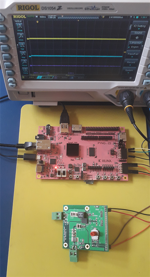
Real world example: Control a GaN half-bridge that needs 8-10 ns dead band between upper and lower FET


Video: the design in action:
I documented my learning path, starting the day after I got the board as a present from balearicdynamics on May 30, when we visited the Drongen maker space:
Top Comments
-

Jan Cumps
-
Cancel
-
Vote Up
+1
Vote Down
-
-
Sign in to reply
-
More
-
Cancel
Comment-

Jan Cumps
-
Cancel
-
Vote Up
+1
Vote Down
-
-
Sign in to reply
-
More
-
Cancel
Children