|
The goal of this blog series is to master the Xilinx Zynq. I'm using the PWM design of my previous post and switch to AXI memory map interface between ARM and FPGA.
I learned this from beacon_dave 's PYNQ-Z2 Workshop - AXI GPIO post. |
ARM/Linux to FPGA interface: from GPIO to AXI memory mapped register
in the previous post, I made a PWM generator in VHDL for the Zynq. I used the ARM EMIO GPIO bus as the interface between ARM and FPGA fabric.
This is a 64 bit bus. I used 8 bits of that bus for the PWM duty cycle, and 4 bits for the dead time of my PWM signal.
Now I'm going to use a different interface: a memory mapped register.
This construct is called AXI in ARM speak. It is not Zynq specific. If you have an ARM controller that has memory-mapped registers to talk to a peripheral (SPI, counters, I2C, ...), it may use AXI too on the silicon.
The most obvious difference when you use an AXI design, is that you set a value on a memory location.
In my previous design, with GPIO, you would set duty cycle (8 bits) and dead time (4 bits) in this way:
# duty cycle 50%
bit_0.write(1)
bit_1.write(1)
bit_2.write(1)
bit_3.write(1)
bit_4.write(1)
bit_5.write(1)
bit_6.write(1)
bit_7.write(0)

# dead time 8 clock ticks
bit_8.write(0)
bit_9.write(0)
bit_10.write(0)
bit_11.write(1)
With memory mapped register and AXI:
#duty cycle 0 - 255 (0 - 100%)
pwm_register[0:8].write(127)
#dead time 0 - 15 (clock cycles)
pwm_register[8:12].write(8)
Changes to the Design
The PWM VHDL does not change. Latest source on github: https://gist.github.com/jancumps/36f21e89bfb8e44f3dba7bf014ffd198
For the processing block, you have to enable AXI and not enable GPIO.
The easiest way to do that is to start from a fresh Zynq block, and run the block automation after that. That's it.
If you replicate this exercise: there is a mistake. The interconnect reset should go tho the first reset of the AXI Interconnect IP.
All other resets should connect to the peripheral reset pin.
You need 3 additional blocks, Reset, AXI interconnect and AXI GPIO.
The interconnect will interface the protocols beteen PS and PL (beacon_dave explains it in his post). The Reset is also part of the integration management
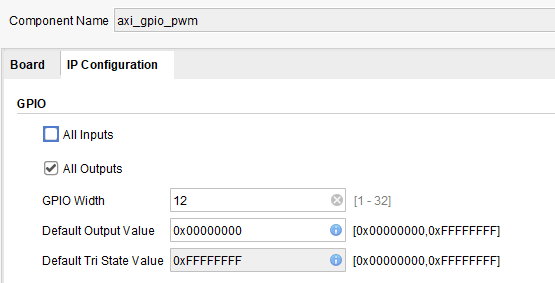
The AXI GPIO is our access to the 12 bit memory location.
From here on, we're back on common ground. Just like in my previous post, we'll use 2 slices to extract the 8 bits for duty cycle and 4 bits for dead time
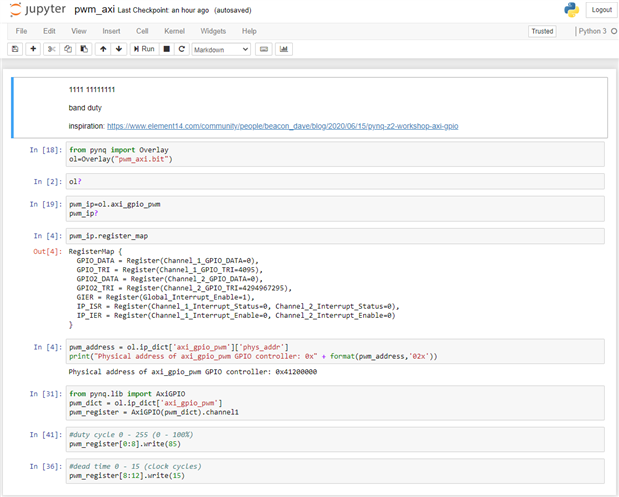
The Python code in the Jupyter book
from pynq import Overlay
ol=Overlay("pwm_axi.bit")

from pynq.lib import AxiGPIO
pwm_dict = ol.ip_dict['axi_gpio_pwm']
pwm_register = AxiGPIO(pwm_dict).channel1

#duty cycle 0 - 255 (0 - 100%)
pwm_register[0:8].write(85)
#dead time 0 - 15 (clock cycles)
pwm_register[8:12].write(15)
Tip: you can set duty cycle and dead time in a single call:
pwm_register[0:12].write(0b100010000000)
I'm attaching the Vivado project and the Jupyter notebook to this post.


Top Comments
-

Jan Cumps
-
Cancel
-
Vote Up
+2
Vote Down
-
-
Sign in to reply
-
More
-
Cancel
Comment-

Jan Cumps
-
Cancel
-
Vote Up
+2
Vote Down
-
-
Sign in to reply
-
More
-
Cancel
Children