

 | Enter Your Electronics & Design Project for a chance to win a Grand Prize for Originality, a Tool Set, and a $100 Shopping Cart! | Project14 Home |
| Monthly Themes | ||
| Monthly Theme Poll |

 |
 |
Congratulations to koudelad for "No lies" IR Thermometer! You are the winner of the Grand Prize package of an 18-Piece Journeyman Tool Set and a $100 Shopping Cart!
Congratulations to fmilburn for Working Prototype of a Kelvin (4-Wire) Milliohm Meter, dubbie for TinyDVM, and dougw for µBOSS .... Test Instrumentation ... micro:bit! You are First Place Winners of the 6-Piece Trim Out Tool Set and a $100 Shopping Cart!
"There is a great satisfaction in building good tools for other people to use." - Freeman Dyson, theoretical physicist and mathematician known for work in quantum electrodynamics, solid-state physics, astronomy and nuclear engineering.
"A tool is but the extension of a man's hand, and a machine is but a complex tool. And he that invents a machine augments the power of a man and the well-being of mankind." - Henry Beecher, pioneering American anesthesiologist, medical ethicist, and investigator of the placebo effect at Harvard Medical School.
"It's best to have your tools with you. If you don't, you're apt to find something you didn't expect and get discouraged.” - Stephen King, author of horror, supernatural fiction, suspense, science fiction and fantasy.
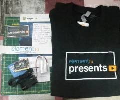
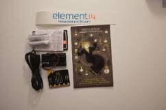
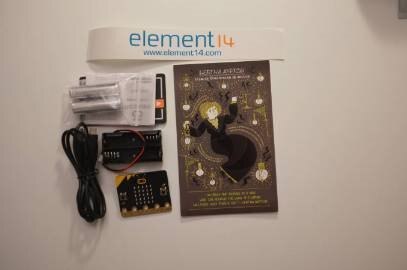
Thanksgiving has come and gone here in the Chicago office and the holiday season is getting ready to kick off in full swing. In the US, it's a time when we show our gratitude for the things we are thankful for, such as family and the friends that we make our family, before glutinously scarfing down a turkey and whatever else we could crowd onto our plate. Before we did that we sent out some micro:bit as part of Project14 | Test Instrumentation: Tool Kit Prizes: micro:bits for Testing Tool: bits! We also added Tool Kits to all our prizes because we all know how much you love your Test & Tools.
Project14 is a program that by its very nature is inclusive. It is after all, a program whose vision is that we can only be our best selves when what makes us different, is what makes us unique and original.
It's our belief that the differences we have are opportunities to learn from one another as a way to improve, not something that separates us. You have to have leadership that supports those values and we are certainly thankful that we have that here. It really starts out at the top with dkibbey, the head of the element14 community and e14mindi . Two fearless leaders with two different styles that I have learned so much from and am grateful for. I'm also thankful for Sarribas , who I only started working with when this program began, and has worked tirelessly in supporting the program, month in and month out. Although she's in Spain and we've never been in the same physical location, she has become one of my favorite people to work with. Hard to imagine this program succeeding without her tireless effort and support as social lead.
Without further adieu here are your winners....
| {tabbedtable} Tab Label | Tab Content | ||||||||||||
|---|---|---|---|---|---|---|---|---|---|---|---|---|---|
| The Winners |
The Grand Prize Winner
"No Lies" IR Thermometer by koudelad
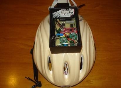
koudelad likes thermometers. As he sees it, temperature is one of the most popular things to measure whether its in your home, work place, or in machines. With his wife expecting, he decided to welcome him or her into the world with a body thermometer. After finding no luck with commercial options, he decided to make one himself as the perfect gift to give their future electronics enthusiast. First, there is no value specified for the emissivity set in the IR sensor. Second, there are usually two types of measurements: for body use and general-purpose home use. "No lies" IR Thermometer was his solution.
An infrared thermometer measures the amount of thermal radiation by the object being measured. It is based on an effect called black-body radiation, which is a thermal electromagnetic radiation, that has a specific spectrum and intensity, depending on the body’s temperature. Most of the emission is in the infrared region, but with increasing temperature get to the human visible light region. To make things more complicated, real objects never radiate as ideal black-bodies. They emit a fraction of what would the ideal black-body emit. This is described as emissivity, meaning how well the real body radiates, compared to the black body. Emissivity also depends on various factors, but in common engineering, it is considered a constant.
Also on Project14 by koudelad:
The First Place Winners
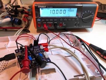
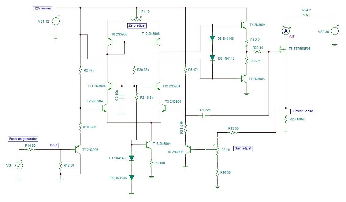
Working Prototype of a Kelvin (4-Wire) Milliohm Meter by fmilburnThis is the prototype for an inexpensive but reasonably accurate meter for measuring resistance in the milliohm range. The development was documented in detail and links can be found at the bottom of this post. The prototype is functional but still under development so continue to watch this space if you are interested in the final outcome.
Features
Also on Project14 from fmilburn:
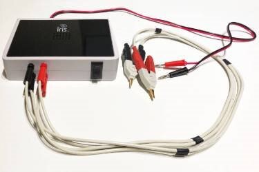
Tiny DVM by dubbie
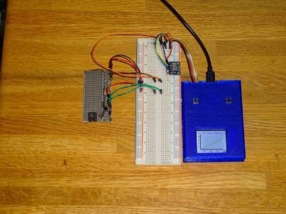
dubbie is using the Arduino MKR 1010 WiFi controller for the TinyDVM as a way of testing it. After looking at several OLED displays he settled on the SparkFun Micro OLED breakout board. It seemed to have a reasonable size display and because it was supplied as a breakout board it was easy to prototype. It has a graphical display so I can try out different sizes of text display to see which is best. There is also the added possibility of being able to use some sort of graphical voltage display, such as voltage against time. SparkFun also provided a detailed hook up document along with an extensive library for drawing both text and graphics on the display.
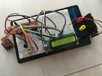
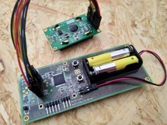
µBOSS .... Test Instrumentation ... micro:bit by dougw
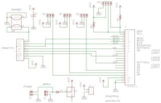
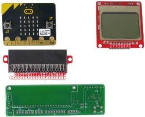
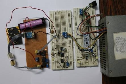
This Project14 blog is about turning a BBC micro:bit into a test instrument. dougw calls this a micro:bit of sense system or µBOSS. The micro:bit already has a nice set of sensors but they aren't very easy to read on the built in LED display, so his thought is to display all the sensor readings on an LCD, turning it into a test instrument that has the following capabilities:
Additional features include a lithium-polymer battery and a rectangular 3D printed case that allows flat surfaces to be measured for levelness. The electronic design is based on a custom interconnect PCB that hosts a micro:bit connector, an LCD footprint, a power switch, a analog input connector and a charging connector.
| ||||||||||||
| Runners Up |
Runners Up
tinyMonster - Analog Precision opto-isolator by mahmood.hassan
Maximum and minimum possible output voltage are limited to integrate it with microbit analog input and to avoid any damage to microbit. Maximum output voltage will not exceed microbit analog input maximum limit 3.6V and similarly minimum output voltage will not go below 0V even if negative voltage is applied at the input. Before connecting it to microbit the supply voltage at microbit 3V ring is tested and it is ~3.2V instead of 3.3V when supplied through usb and it was also momentarily dropping (~3.1) when something is displayed on leds matrix. So in order to avoid any possible damage to analog input, the maximum output of opto isolator circuit is limited to 3.0V. Because maximum possible IO voltage for microbit is VDD+0.3 volt. After Calibration and max min limit setting, it is tested at different voltages to check output linearity.
Also on Project14 by mahmood.hassan:
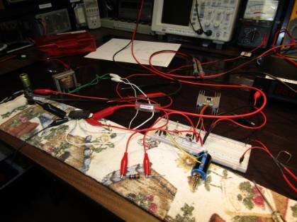
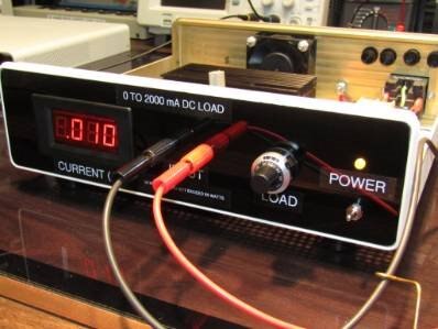
A Simple DC Electronic load for the experimenter's Shop. by jw0752
In making this project jw0752 tried to use as many salvage and off my shelf parts as possible. The unit enclosure case began life as a control box for a camera in a Dental Office. The Ammeter, which will read down to 1 mA is cheap. The most expensive part on the unit is the Bourns 10T 10K potentiomenter which was bought with the hope that its an original. He likes to begin these projects by taking an inventory of potential parts and resources.
Project PITS by three-phase
Also see: Project PITS update
PITS is a Pickup Indicator Test System I am developing for use with injection test sets on older electronic analogue designed protection relays. This concept is not original, Omicron have such a product for use with their test set. The unit is very expensive and to my knowledge can only be used on Omicron test sets. Megger do not offer a pickup indicator detector for their test sets.This version is universal and will function with both the Omicron and Megger test sets
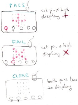
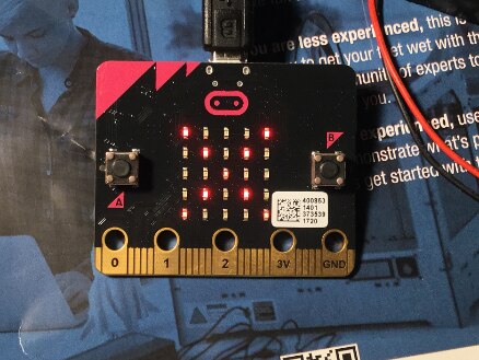
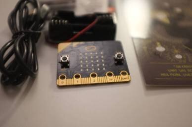
micro:bit as Pass / Fail indicator in an automated test setup by Jan Cumps
Jan Cumps' first micro:bit project is to turn it into a LabVIEW test device as a pass and fail indicator. It will perform two functions:
It is programmed using C / C++ and the learning experience of using the micro:bit is blogged about.
Also on Project14 by Jan Cumps:
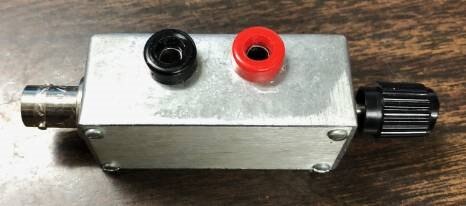
MinMax - Calibration Box by rsc
Add a micro:bit, some switches, and display, and you have a programmable analog test instrument. When working with data acquisition systems, many times a signal doesn't behave as expected. When diagnosing the problem, it's nice to have a reference voltage to test your inputs. I made up this quick "MinMax" test box for quickly testing analog inputs. The MinMax is built from four simple parts, a set of banana jacks for input voltage, a BNC output jack, a variable resistor, and a box. I have one with a 1K 1 turn pot, and one using a 10 turn 100K pot for testing opamp circuits. VCC can be 3.3V, 5V, 12V, or whatever your circuit needs. I made one up with a 1A analog meter inline also. *** Note *** there is not a current limiting resistor inline, or a fuse, so if you short the BNC, you can short your power supply.
To use the box:
1) Apply power and ground to the red(+) and black(-) banana jacks 2) Connect BNC to DAQ input, and connect in parallel to voltmeter if needed. 3) Adjust output from 0-100%
Simple resistance measurement with the micro bit and voltage divider by kk99
This demonstrates a simple example of usage micro bit to measurement of resistance. I have used for this purpose a voltage divider with reference resistance set to 1 k Ohm (1% 50ppm). Output voltage of this divider is connected to the analogue pin number 2. The code was created in python. For this purpose I used a page python.microbit.org, which allow to generate output .hex file which I used to program my microbit. Code is really simple. If user presses button A, we are reading value of voltage from PIN 2. If this value is correct then calculation of resistance is performed and user sees on display the resistance value. If user presses button B the display will be cleared.
| ||||||||||||
| Honorable Mention |
Honorable Mention
A Transistor Load by jc2048
Op amps are for wimps –this member is going for the hard stuff - a transistor design. Just kidding. Not about the transistors… If you just want to build a load then be sensible and use op amps, particularly if you want precision from it. The reason he’s doing it with transistors is to see what he can manage in the way of a design, putting some of what he’s learned in the past to the test. It's also going to be a vehicle for looking at more transistor circuit building blocks.
SCPI on a Linux Board - Part 4b: TCP/IP SCPI and Instrument Service 100% Working by Jan Cumps
This post is about building an SCPI electronics lab instrument for Linux. He's now completed both read and write functionality.
Wireless voltage measurement with microbit by kk99
Micro:bit has a BLE interface which we could configure to work as UART service. In this example value of voltage on PIN P2 is transmitted via Nordic UART service present on micro:bit on every one second. When Bluetooth device is connected to micro:bit the connection icon is displayed on the LED display. Source code included!
Micro:bit VI Curve Tracer Intro by ralphjy
ralphjy proposed using a Micro:bit to control a programmable current sink to implement an VI curve tracer for the November Project14 DIY Test Instrumentation competition. Unfortunately, I had some personal issues that prevented me from being able to enter the competition. Coming into this he viewed the biggest challenge being around code as he's new to the micro:bit ecosystem. In particular, interfacing the I2C DAC and the SPI LCD Display. If this were an Arduino it would be straightforward because of all the available libraries. He decided to make the tool modular to make it more flexible. The first module will incorporate the Micro:bit and the display shield. The second module will include the I2C DAC and programmable current sink. The modular approach allows me to add other functionality later.
|


What's Happening Now
There's always stuff going on in the community and the best ideas always come from you. Suggest your idea in the Monthly Poll! and vote on the themes you want to do projects on. We're offering PocketBeagles for Project Proposals that use them in our Wearable Tech and you can show your love for analog in Back to Analog!
| Wearable Tech | Back to Analog |
|---|---|
| Project14 | Build Wearable Tech: PocketBeagles for Project ideas! | Build a Device that Takes You Back to the Days of Analog! |
|
|
| Wearable Tech | Back to Analog |

Starting December 3rd, we'll be having our second annual Holiday Special. The theme is Merry Boxes and LED Displays. The goal is to Spread Mirth and Merry through Music and LED displays over the holiday season. An Oscilloscope Grand Prize to the project that brings the most joy to the world plus a Home Lab Gift to Give. Shopping Carts and Maker Kits for 3 First Place Winners plus Shopping Cart Gift to Gives! The competition will run till January 15th.
| The Holiday Special: Merry Boxes and LEDs | |
|---|---|
| Project14 | Holiday Special: Spread Mirth and Merry Through Music and LED Displays! | Merry Boxes & LEDs |
 |  |
| Gift to Keep: Ben Heck's Oscilloscope | Gift to Give: A Home Lab Tool Kit |
 |  |
| Gift to Keep: A Maker Tool Kit Bundle Plus a $100 Shopping Cart | Gift to Give: A $100 Shopping Cart |
Thank you for continued support of Project14 !
Its been a great year and we're going to close it out with a bang!
In the comments below:
Top Comments
-

kk99
-
Cancel
-
Vote Up
+7
Vote Down
-
-
Sign in to reply
-
More
-
Cancel
Comment-

kk99
-
Cancel
-
Vote Up
+7
Vote Down
-
-
Sign in to reply
-
More
-
Cancel
Children