 Connectors Essentials Series - Part 3
The tremendous growth of wireless communication around the world has spawned the development of more types of RF connectors than was ever imaginable a mere twenty years ago. Radio frequency connectors today are providing critical links to a substantial amount of equipment, including networking, cellular communications, radio frequency identification, global positioning systems, mobile radio systems and many more. Understanding the factors that impact the selection as well as the design of RF connectors is essential knowledge for a design engineer who works with RF circuits. This learning module explores the features and applications of the most common types of RF connectors.
Related Components | Test Your Knowledge 
sponsored by
2. Objective
The objective of this learning module is to provide you with the essentials of RF connector technology. You will first review the basics of electromagnetic wave theory. In the later sections, you will gain an understanding of radio waves, coaxial transmission lines, and the common types of RF connectors and their applications.
Upon completion of this module, you will be able to:
- Define the electromagnetic spectrum
- Discuss the elements of RF coaxial transmission Lines
- List the components, coupling styles, and termination types of coaxial connectors
- Explain the importance of RF performance specifications
- Identify the most common types of RF connectors and their applications
3. The Electromagnetic Spectrum
Radio frequency and wireless communication devices have been built for over a century. Many scientists contributed to their development, including Sir Oliver Lodge, Alexander Stepanovich Popov, Sir Jagadish Chandra Bose, and many others. But it was Guglielmo Marconi’s experimental broadcast of the first transatlantic radio signal in 1901 that ultimately led to the commercial viability and world-wide adoption of RF technology. Devices based on RF technology ranging from radio, TV, cellular and the Internet are so common today that we can hardly imagine a world without them. Before discussing the different types of RF connectors in this learning module, let’s begin with a brief review of the theory behind radio frequency devices, beginning with the Electromagnetic (EM) Spectrum.
Decades before Marconi's first transatlantic radio broadcast, Scottish scientist James C. Maxwell demonstrated, in the 1860s, that time-varying electric and magnetic fields cause electromagnetic waves to travel in a vacuum at the speed of light. Twenty years later, Heinrich Hertz went on to apply Maxwell's theories and experimentally prove the existence of radio waves in the late 1880s.

Electromagnetic waves are the result of self-propagating, transverse oscillations of electric and magnetic fields. These fields are perpendicular to each other and to the direction of the wave. Once formed, this electromagnetic energy travels at the speed of light until it interacts with matter.
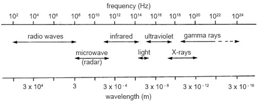
The discovery of electromagnetic waves led to the identification of an entire range of EM waves that are together called the Electromagnetic Spectrum (EM). These waves are radiant energy, resulting from electromagnetic interactions. While EM waves are continuous in nature, scientists typically divide the EM spectrum into discrete segments called bands. The following table describes the EM spectrum's frequency bands:
| Frequency (f) | Wavelength (λ) | Band | Description |
|---|---|---|---|
| 30-300 Hz | 104 to 103 km | ELF | Extremely Low Frequency |
| 300-3000 Hz | 103 to 102 km | VF | Voice Frequency |
| 3-30 KHz | 100 to 10 km | VLF | Very Low Frequency |
| 30-300 KHz | 10 to 1 km | LF | Low Frequency |
| 0.3-3 MHz | 1 to 0.1 km | MF | Medium Frequency |
| 3-30 MHz | 100 to 10 m | HF | High Frequency |
| 30-300 MHz | 10 to 1 m | VHF | Very High Frequency |
| 300-3000 MHz | 100 to 10 cm | UHF | Ultra High Frequency |
| 3-30 GHz | 10 to 1 cm | SHF | Super High Frequency |
| 30-300 GHZ | 10 to 1 mm | EHF | Extremely High Frequency (Millimeter Waves) |
Electromagnetic waves travel at the speed of light in a vacuum. These waves are described by their relationship between frequency (f) and wavelength (λ). Their relationship is shown in the following equation:
(with c = 3.0 x 10⁸ m/sec)
Since the speed of light is a constant (3.0 x 10⁸ m/sec), the equation predicts that as the frequency of an electromagnetic wave increases, its wavelength decreases, and vice versa.
4. Radio Frequency Waves: AM/FM Bands
Radio waves are one of the many types of electromagnetic (EM) radiation or energy; they appear at the lowest frequency portion of the electromagnetic spectrum. They have wavelengths between 1 millimeter and 100 kilometers (or 300 GHz and 3 kHz in frequency). While radio waves occur naturally in the world, radio waves can be generated by RF devices used in fixed and mobile radio communication, broadcasting, radar, communications satellites, computer networks and more.
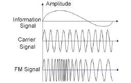
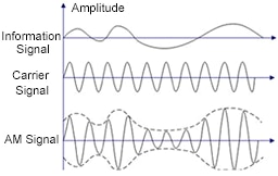 AM and FM bands are the part of the electromagnetic spectrum used for radio broadcasting. In the AM band, radio waves, called "carrier waves," are used to broadcast commercial radio signals in the frequency range from 540 to 1600 kHz. The abbreviation AM stands for "amplitude modulation," which is the method for broadcasting radio waves by varying the amplitude of the carrier signal to be transmitted. The resulting wave has a constant frequency, but a varying amplitude.
In the FM band, the carrier waves are used to broadcast commercial radio signals in the frequency range from 88 to 108 MHz. The abbreviation FM stands for "frequency modulation," which is the method for broadcasting radio waves by varying the frequency of the carrier signal to be transmitted. The resulting wave has a constant amplitude, but a varying frequency.
RF technology continues to demonstrate itself as a durable technology with its growing impact on IoT wireless connectivity. Much of today's most popular wireless equipment operate in the 2.4-GHz radio band, including Wi-Fi hot spots and home wireless routers, ZigBee, Bluetooth, some cordless phones, among others. Sub-1GHz radio bands are even finding application in the transceivers and microcontrollers designed for this radio band and destined for use in long-range, wireless IoT networks.
5. Coaxial Transmission Lines
A transmission line is a two-conductor structure that supports the propagation of transverse electromagnetic (TEM) waves (i.e., an electromagnetic wave where both the electric and magnetic fields are perpendicular to the direction of wave propagation). It is designed to transmit RF power in the most efficient manner from one point to another. An RF transmission line consists of a source, a load, and the combination of RF cable and connectors. Coaxial lines are the most common type of RF transmission line.
- 5.1 Coaxial Cables
 Coaxial cables are specially constructed cables with a core center conductor, surrounded by a tubular non-conductive insulator (dielectric), which is then enclosed by an braided copper shielding (the outer conductor). The dielectric separates the core inner conductor from the outer shielding conductor. The coaxial cable's outer shielding is typically protected by PVC material.
Coaxial cable is designed to keep the RF waves inside the cable while keeping out magnetic interference. It does so by effectively placing two wires in one structure, each with current moving in opposite directions that cancel out the currents due to the proximity effect thereby preventing RF radiation. Coaxial cable is ideal for applications where attenuation must be kept to a minimum and the elimination of outside interference is critical.
- 5.2 Impedance Matching
Transmission lines must be impedance matched over the entire coaxial structure in order to prevent reflections of the signal at the line terminations. If the impedances aren’t matched, maximum power will not be delivered (from source to load) and standing waves will develop along the line.

In a transmission line, the source, line and load impedances must be matched for maximum power transfer to occur. In other words, ZS = Z0 = ZL
- 5.3 PCB Transmission Lines
Transmission lines can also be constructed utilizing printed circuit board technology. The substrate of the printed circuit board functions as the dielectric and separates the two conductors. The first conductor is typically a narrow etch, while the second conductor is the ground plane. The most popular types of printed circuit board transmission lines are: microstrip, stripline, coplanar waveguide and slotline.
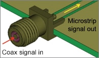
Coaxial RF connectors allow a cable to be connected to another cable or component (e.g, printed circuit board) of the RF transmission line structure. There is a wide variety of coaxial connectors designed to fit with different types of coaxial cable. Coaxial connectors will be discussed in the next section.
6. Coaxial Connectors
In this section, let's discuss the components, coupling styles, and termination types of a typical coaxial connector.
- 6.1 Components
- Inner Conductor (Center Conductor): functions similar to a terminal in an electrical connector; it carries the main circuit signal.
- Dielectric: functions as an insulating spacer between the inner and outer conductors.
- Shielding (Outer conductor): provides shielding that keeps interference outside the connector while keeping desirable currents inside. It’s held at ground or reference potential for a circuit path return.
- 6.2 Coupling Style
The coupling style is the method used to mate a coaxial plug to a coaxial connector or receptacle. There are four types of coupling mechanisms used with RF connectors, including: Threaded, Bayonet, Snap-On and Slide-On.
In general, threaded styles maximize mating security. They are used in high vibration environments. Snap-on devices provide the quickest mating. Bayonet couplings offer a compromise between ease of use and mating security. Slide on coupling provides quick and easy installation.
The coupling style also impacts performance. As with electrical connectors, higher performance RF products require exceptionally tight, stable mating interfaces to minimize noise and optimize energy transfer. Traditionally, threaded couplings have provided this integrity. Today, however, non-threaded coupling technology have advanced significantly to provide the same benefit and often in a small footprint.
- 6.3 Terminations
Coaxial cables are typical terminated with RF connectors. Coaxial connectors are designed to maintain a coaxial form across the connection and have the same impedance as the attached cable. Coaxial connectors can be terminated in the following ways: Plugging, Soldering, Crimping, Clamping, Pressing and Threading.
7. Performance Specifications
Now that you understand the physical features of coaxial connectors, let's consider their performance. There are many factors that determine the performance of RF coaxial connectors, but the four main specifications are:
- Frequency range: Each coaxial connector series supports a specific frequency range. A connector's frequency rating is typically determined by the internal geometry of the coaxial structure with which it is used. Conductor sizes and the type and amount of insulation between them determine this spec. In general, higher frequency connectors tend to be smaller in diameter and have tighter tolerances.
- Impedance: Impedance can be thought of as the total resistance a system offers to the flow of RF waves. For maximum power transfer of RF energy, impedance should be matched throughout the entire coaxial structure. If the coaxial structure is not impedance matched, parts of the RF waves reflect back toward their source, decreasing energy transfer and flow efficiency. In addition, the reflections may distort the waves to the point where the information they carry cannot be accurately interpreted. Most RF application manufacturers design their products for either of the two industry-standard cable impedance ratings: 50 Ohm or 75 Ohm. 50 Ohm cable is commonly used for radio transmitters and receivers, laboratory equipment, and data communications. 75 Ohm cable is typically used in video applications, CATV networks, TV antenna wiring, and telecommunications.
- Voltage standing wave ratio (VSWR): While it's theoretically possible to achieve perfect impedance matching, it's not usually cost effective. There will always be reflections. How much reflection an RF connector introduces is stated in its VSWR (Voltage Standing Wave Ratio) specification. VSWR expresses the reflected signal as a ratio to the pure signal; it measures the impedance matching of loads to the characteristic impedance of a transmission line. Impedance mismatches result in standing waves along the transmission line. An ideal VSWR would be 1.00, indicating that all RF energy passes through the connector. The VSWR should be as low as possible.
- Intermodulation distortion: intermodulation distortion (IMD) is the amplitude modulation of signals containing two or more different frequencies, caused by nonlinearities in a system. This expresses the signal distortion from factors caused by poor design and manufacturing, bad grounds, corrosion, low contact pressure, etc. These problems generate unwanted frequencies that distort the original signal, inhibit its ability to carry data without errors, and impede accurate demodulation. Some typical contributions to intermodulation distortion are: oxidized metal contact surfaces, current saturation, and oil or grease layers between contacts.
8. Types of RF Connectors
There are many types of coaxial connectors. This learning module will discuss on the most common types, categorized by size.
- 8.1 Miniature RF Connectors
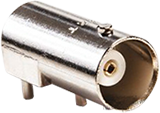
MOLEX 73100-0105 RF Coaxial Connector BNC Coaxial Right Angle Jack Solder 50 ohm Phosphor Bronze
The BNC connector is one of the most common types of coaxial cable connectors. BNC connectors are used with miniature-to-subminiature coaxial cable in radio, television, and other radio-frequency electronic equipment, test instruments, and video signals. It features two bayonet lugs on the female connector. Mating is fully achieved with a quarter turn of the coupling nut. BNC Radio Frequency (RF) Connectors ensure proper operation and signal integrity throughout the entire broadcast-transmission line. They can transmit signals up to 12 GHz and exceed performance requirements of serial-data transmission for high-speed, high-definition TV (HDTV), HD video and broadcast applications.
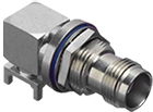
MOLEX 73216-2710 RF Coaxial Connector TNC Coaxial Right Angle Jack 50 ohm Phosphor Bronze
The TNC connector is a threaded version of the BNC connector designed for demanding, high-vibration and harsh environments. It is commonly used in mobile communications, avionics and antenna ports for wireless base units. TNC miniature performs at a constant 50 Ohm impedance. The stability of the threaded coupling allows the connectors to perform up to 11 GHz with improved resistance to adverse environments. It has better performance than the BNC connector at microwave frequencies.
- 8.2 Subminiature RF Connectors

MOLEX 73298-0030 RF Coaxial Connector BMA Straight Plug Crimp 50 ohm RG55 RG142 RG223 RG400
BMA connectors are an ideal solution for high-frequency performance rack and panel RF applications up to 22 GHz. BMA connectors are available in both fixed and float mount versions to allow for rack and panel mount applications where axial and radial float are needed. The BMA design has protected spring contacts that assure reliable, damage-free mating. They have blind mating capabilities up to 1.27mm axial and 0.5mm radial misalignment.

Type F Connector
The Type F connector is a coaxial RF connector commonly used for "over the air" terrestrial television, cable television and universally for satellite television and cable modems. In the 1970s, Type F connectors became commonplace on VHF television antenna connections in the US, as coaxial cables replaced twin-lead cables. They have a threaded coupling style to ensure the connector will not decouple in high vibration applications. They are designed for use from DC to 4 GHz.
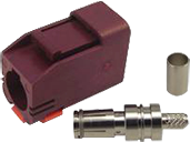
MOLEX 73403-6263 RF Coaxial Connector FAKRA II SMB Coaxial Straight Plug Crimp 50 ohm RG174 RG316 Phosphor Bronze
FAKRA and FAKRA II SMB connectors are specifically designed for automotive telematic applications. Standard uses for FAKRA connectors are coaxial connections on devices with external antennas such applications include SDARS, Cellular, GPS Navigation, key-less entry and satellite radio. A 360° rotation inside the plastic shroud provides ease-of-routing and less stress on the cable. A secondary locking latch delivers easy cable routing between antennas and multi-media units. The connector is color coded and keyed shrouds prevent mismating and helps guide proper connection. It has a frequency range from DC to 4 GHz.

SMP Jack SMP Plug
The ever increasing need for higher density and lighter weight electronics within today's systems requires compact connections. SMPM RF Blind-Mate board-to-board and cable connections deliver the needed density in a high-performance connector. Providing superior frequency performance from DC to 65 GHz, the SMPM connector also compensates for the axial and radial misalignment issues inherent with board-to-board mating.
SMP subminiature connectors offer excellent performance from DC to 40 GHz. PCB mount, cable mount and in-series adapters provide an interconnect solution for board-to-board and blind mate applications while maintaining package density. SMP connectors are also available in multi-port solutions. Interface styles include smooth, limited detent and full detent to cover a wide range of applications.
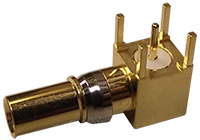
MOLEX 73174-0040 RF Coaxial Connector DIN 41626 DIN 1.0/2.3 Right Angle Jack Through Hole Vertical 50 ohm
DIN 1.0/2.3 connectors are compact RF/microwave connectors for applications where space limitation is a factor. They allow up to 1.00mm of axial engagement tolerance, providing excellent flexibility when mating orthogonal PCBs. They enable transferring multiple RF signals across mated boards in a single assembly. 50 and 75 Ohm designs ae available. Some versions of the 50 Ohm design are capable of operating to 10 GHz. DIN 1.0/2.3 connectors are also available in a Modular Backplane System that enables system designers to improve system routing of RF signals for board-to-board communications. They conform to CECC 22 230, DIN 47297 and DIN 41626.
Developed as an alternative to the threaded SMA connector, the QMA connector is one of the most popular coaxial connectors in use today. Performance is comparable to a threaded SMA with the benefit of a faster installation and removal as well as higher density. This design can save handling time because it allows quick mating and demating without tools. Due to the smaller overall size, it can save the operating space and allows for high density arrangement. To make cable routing easier, it can rotate 360 degrees after installation. It is rated from DC to 18 GHz.


SMA Jack SMA Plug
SMA Connectors are high-performance subminiature connectors for microwave frequencies. The threaded coupling insures uniform contact of the outer conductors, which enables the SMA to minimize reflections and attenuation at higher frequencies while providing a high degree of mechanical strength and durability. SMA connectors are available in brass, beryllium copper and stainless steel materials. SMA Connectors are optimized for high performance, operating to 27 GHz.


SMB Jack SMB Plug
SMB connectors are a subminiature connector series designed for applications operating to 4 GHz and are available in 50 and 75 Ohm versions. This series includes a snap on interface, controlled by industry standard specifications and is easy to connect and disconnect. Mechanical stability provided by the SMB interface, and its relative small size allows uses in applications where space is limited.
- 8.3 Microminiature RF Connectors


MMCX Jack MMCX Plug
Microminiature connectors are finding their way into an ever growing list of smaller, denser applications, such as switching equipment, cellular handsets, and mobile computers. Ideal for space-critical applications, MMCX connectors are compact and lightweight connectors that provide reliable electronic performance from DC to 6 GHz. Their mechanical stability is maintained via a snap-on interface that does not use slotting in the outer conductor. Typical applications include wireless/PCS devices, telecommunications, GPS receivers and consumer electronics. For medical MRI applications, non-magnetic versions are available.


MCX Jack MCX Plug
MCX subminiature snap-on connectors offer a stable and durable connection. Their subminiature design allows other electronic assemblies to be densely packaged on the PCB. MCX connectors are approximately 30% smaller than SMB connectors. They are available in both 50 and 75 Ohm versions and provide good electrical performance to 6 GHz. These connectors are used in telecommunications systems as well as wireless and GPS applications. For medical MRI applications, non-magnetic versions are available. Multi-port MCX connectors for coplanar board-to-board and cable-to-board applications.
- 8.4 Ultra-microminiature RF connectors


SSMCX Jack SSMCX Plug
Super Snap-on MCX (SSMCX) or ultra microminiature connectors are designed for electronic applications with size and weight limitations while maintaining good RF characteristics. SSMCX connectors are approximately 35% smaller than MMCX connectors; they are available in 50 and 75 Ohm versions. The extremely small size makes SSMCX connectors are an ideal solution to create multi-port, high-density RF applications.They are commonly used in board-mount applications, such as handheld devices and notebook PCs, where the jack is edge-mounted. They have a frequency range from DC to 6 GHz. A low-loss cable version is available to provide greater signal strength. It has a mechanical latch to ensure connectors are securely mated and to prevent accidental un-mating. Metal PCB board-lock posts provides proper PCB alignment, added strength, secure PCB retention during and after soldering.
- 8.5 Medium RF Connectors

MOLEX73100-0033 RF Coaxial Connector N Coaxial Straight Jack Crimp 50 ohm RG58 RG141 RG303
Type N connectors balance frequency and power by providing a low-loss interconnect up to 11 GHz for high-power RF applications. Type N connectors have a miniature classification; however, it is medium size in use. They accommodate a wide range of medium to miniature-sized RG coaxial cables in a rugged medium-sized design. Type N connectors can provide low-loss interconnects to 11 GHz, optimized precision versions are available up to 18 GHz. The screw-type coupling combined with the larger size, provides a robust design and proper fit for some larger coaxial cables. A durable threaded coupling ensures connector will not decouple in vibration intention applications. Applications include broadcast electronics, aerospace, telecommunication base stations and the passive/active components used in base stations.
- 8.6 Large RF Connectors

DIN 7/16 Jack DIN 7/16 Plug
7/16 DIN connectors are designed for rugged, low-loss, high-power wireless infrastructure systems. They are designed for a wide range of cables, including corrugated styles. Silver or tri-metal (Copper, Tin and Zinc) plating is used for low Inter-modulation Distortion (IMD). The tri-metal plating is tarnish resistant and durable and provides abrasion resistance comparable to nickel with far better electrical performance. Tri-metal plating alloys are non-magnetic which is critical for low IMD. They are rated from DC to 7 GHz. They have an easy-Hex coupling nut to allow toolless application.
- 8.7 Multi-Port (Ganged) RF Connectors

Ganged Jack

Ganged Plug
As applications become increasingly smaller and functionality requirements continue to grow, there has become a need for greater density and convenience. Multi-port (Ganged) RF connectors permit mass mating of RF circuits. They mitigate the risk of I/O coax connection failure in high-vibration environments with rugged and compact MPRF connectors. Cable weight under vibration can compromise connections and cause system failure in small multi-port connectors when terminations twist and/or move within the housing. Designed with dual side latches, MPRF connectors ensure reliable I/O connection by preventing cables from moving or twisting within the ruggedized housing even in high-vibration environments.
*Trademark. Molex is a trademark of Molex Corporation. Other logos, product and/or company names may be trademarks of their respective owners.
Test Your Knowledge
Connector Skills 3

Are you ready to demonstrate your RF Connectors knowledge? Then take a quick 20-question multiple choice quiz to see how much you've learned from this module.
To earn the Connectors 3 badge, read through the module to learn all about RF connectors, complete the quiz at the bottom, and leave us some feedback in the comments section.

