|
||||||||||
|
||||||||||
1. Introduction
We are living in the age of mechatronics — the intersection of electronics, mechanical engineering and advanced computer control. Nothing better characterizes this age than the whirlwind of innovation in the area of robotics. Without electronics, robots could not exist in their present form; conversely, without mechanical, electrical and software engineering, a robot would be nothing more than a Lost in Space stage prop from a 1960s American TV show.
When electronics design engineers work at their benches, huddled over their breadboards and test equipment, they may increasingly be part of the mechatronic design process, which places value on a cross-functional, interdisciplinary knowledge base. You may not feel touched by the age of mechatronics right now, but keep in mind that the Internet of Things is one of the new and evolving engineering disciplines that lives on the edge of mechatronics.
Hence, electronics, robotics, and IoT engineers may one day need to develop a combination of mechanical and electronic knowledge that characterizes this age. To that end, element14 decided to offer a learning module on circuit breaker essentials for an electronics design engineer community. This learning module will provide you with the essential understanding of circuit breaker protection, arc interruption theory, overcurrent protection, and examples of commonly used circuit breakers in mechatronic product designs.
2. Objective
Upon completion of this module, you will be able to:
 Discuss the purpose and functions of circuit breakers
 Describe the theory of circuit interruption
 List the primary means employed to extinguish arcs
 Define the variants of overcurrent protection
 Identify the major components of an "ideal" circuit breaker
 List the types of low voltage circuit breakers
 Understand the ratings, codes, and standards applicable to circuit breakers
3. DefinitionsBack to Top
Let us start this learning module by defining two important terms: (i) circuit breaker and (ii) overcurrent, the latter of which has several variants.
- 3.1 Definition of Circuit Breaker:
The International Electrotechnical Commission Standard IEC 60947-2 defines a circuit breaker as "a mechanical switching device, capable of making, carrying and breaking currents under normal circuit conditions, and also making, carrying for a specified time, and breaking currents under specified abnormal circuit conditions, such as those of short circuit."
In a power distribution system, a circuit breaker is connected in series between a power source and the downstream circuit load. Under normal current conditions, a circuit breaker provides a current pathway to the load. But when a circuit breaker detects an overcurrent condition, it responds by opening or "breaking" the circuit's current path, by disconnecting the power source from the load. After the interruption of the overcurrent condition, the circuit breaker can be reset once the abnormal condition is corrected, and it will again conduct current to the load.
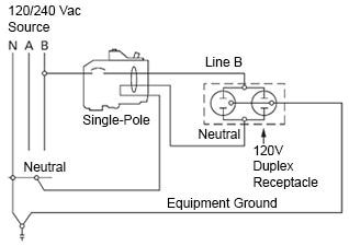
1-Pole Circuit Breaker in series between the 120/240VAC power source and a 120V Load
- 3.2 Definition of Overcurrent
Circuit breakers are designed to open or "trip" to protect a circuit when it senses an abnormal condition such as an overcurrent. Overcurrent is a condition which is produced when an overload, short circuit, arc fault, or ground fault occurs. The effects of an overcurrent condition can be severe, hazardous and dangerous. They include conductor insulation failure, equipment damage, fire, personal injury, electrocution, and property loss.
What exactly defines an overcurrent condition? The term has two main variants:
An overload condition can be defined as (i) the operation of equipment above its normal, full-load rating, or (ii) a conductor operating in excess of its rated ampacity. A persistent overload occurring over a long period of time can cause a buildup of dangerously high thermal heat conditions in conductors and circuit loads. Protection against these dangerous conditions is a primary benefit of a circuit breaker.
A short circuit is an overcurrent condition in which current greatly exceeds the normal full-load current rating of a circuit and occurs in a relatively short period of time. This type of fault condition is typically caused by current deviating from its normal path of flow. The two types of short-circuit fault conditions are (i) direct (phase-to-phase) short and (ii) ground fault (phase-to-ground) short.
 A direct (phase-to-phase) short condition occurs when contact is made between two hot (ungrounded) conductors.
 A ground (phase-to-ground) fault condition occurs when contact (low impedance) is made between a hot wire and ground. Another form of ground fault is an arc fault. An arc fault is a high-power discharge of electricity between two or more conductors. During an arc fault, the air is the conductor. Arc faults are capable of triggering arc flash, a type of electrical explosion or discharge that results from a low-impedance connection through air-to-ground or another voltage phase in an electrical system. Arc faults are often manually started by something creating the path of conduction, or a failure such as insulation break down.
4. TheoryBack to Top
We've established in the previous section that a circuit breaker is a switching device that controls circuit current flow in both normal and fault conditions. So, let's discuss in more detail what occurs during the circuit interruption process.
All circuit breakers have two stable states: (i) zero impedance (closed circuit—acts like a conductor) and (ii) very high impedance (open circuit—acts like an insulator). As such, a circuit breaker can be described as a controlled device that can vary its impedance. To fully understand the variable impedance characteristic of a circuit breaker, let us examine what occurs at the moment of circuit interruption in a fault condition. That is, when the circuit breaker changes state from closed to open circuit.
We will discuss the construction of a circuit breaker in a later section. But for now, let's state that all circuit breakers are constructed with fixed and moving electrical contacts which will pass circuit current to the load. In normal (non-fault) conditions, these contacts are closed or mated to one another and current is flowing through them to the load. When a fault condition occurs, such as a short circuit downstream in the load, the circuit breaker's operating coil energizes, causing the movable contacts to pull away from the fixed contacts, thereby opening or "breaking" the circuit.
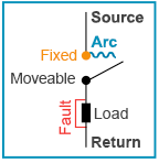
In a fault condition, the heat generated from the separating contacts will ionize the neutral gas particles and create an arc between them.
Since this scenario is a short circuit condition, an immense amount of current flows through the contacts in the moment before they are opened. As the contacts separate, a chain of events occurs: the contact area decreases quickly, causing the current density to rapidly increase. With such a high current density, a corresponding rise in temperature at the contacts will occur. The heat generated from this temperature rise will ionize the neutral gas particles in the air causing a thermal electron emission and creating an arc between the separating contacts. In other words, an arc discharge of electric current will cross the gap between the two contacts. Since there will be a potential difference (albeit small) between the contacts, it can be enough to maintain the arc. Hence, the arc itself provides a path of low resistance to maintain current flow until the arc is extinguished and the contacts have separated (high impedance).
During arcing, the current flowing across the contacts is dependent upon the arc's resistance. Hence, the arc itself functions like a variable resistor: the lower the arc resistance, the larger the current flowing through the arcing contacts, and vice versa. Arc resistance depends on three factors:
 Level of Ionization: the arc resistance increases with a decrease in ionized particles between the contacts.
 Length of the Arc: the arc resistance increases as the length of the arc or the separation of contacts increases.
 Cross Section of the Arc: the arc resistance increases as the area of cross section of the arc decreases.
Obviously, to fully interrupt current flow between the contacts, the arc must be extinguished. This is done in several ways:
 High Resistance Method: arc resistance is made to increase with time so that current is reduced to a value insufficient to maintain the arc. Arc resistance can be increased by lengthening the arc, cooling the arc (facilitating recombination of ionized particles), decreasing the cross section of the arc, or splitting the arc. This method is used in DC circuit breakers.
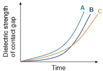
 Current Zero Method: The current zero method is explained by Slepian's Recovery Rate Theory, which considers the arc extinction process in an AC circuit as a "race" between the rate at which the dielectric strength of the gap increases faster than the rate at which the system recovery voltage increases. Every half cycle in an AC circuit, the current decreases to zero, so an arc will be extinguished naturally at these times. But the air gap between the contacts has ions and electrons, thus it possesses a minimal dielectric strength, which is the maximum voltage a dielectric can withstand without breaking down. So, if the rising contact voltage (called the restriking voltage) is large enough it can break down the dielectric strength, resulting in the restriking of the arc for one more half cycle. But if the rate of the dielectric strength of the air gap increases faster than the restriking voltage, the arc will remain interrupted. The rate of increasing the dielectric strength can be obtained by decreasing the ions in the gap, by allowing them to recombine into neutral molecules, or removing them and replacing them with un-ionized molecules. This is done by lengthening or cooling the arc, increasing the pressure, or blasting gas near the arc.
Slepian's Theory considers arc interruption as a race between the rate of increase of the dielectric strength of the contact gap and the recovery voltage after current zero of the power system. Curve B is the system recovery (restrike) voltage after a specific instance of current zero. Curve A occurs when the rate of the dielectric strength of the gap is greater than the rate of increase of the recovery voltage (wins the race - no restrike of the arc), while Curve C occurs when the rate of the dielectric strength is less than the recovery voltage rate (loses the race - arc restrikes). Source: Fundamentals of Power System Protection
5. ConstructionBack to Top
Circuit breakers have been constructed in a variety of configurations, form factors, and rating levels since they began appearing on the market over 100 years ago. The construction of circuit breakers has evolved due to the applications for which they are used, as well as improved manufacturing techniques that emphasize compactness and modularity.
To describe the construction of every circuit breaker would be beyond the scope of this learning module. But modern circuit breakers that electronics design engineers may specify will typically break down into the following sub-components: frame, operating mechanism, trip unit, arc extinguisher, and contacts.
- 5.1 Frame
The frame is a rigidly strong housing that protects, insulates, and isolates current flowing through internally mounted components. It provides terminal points which allow the electrical connection of a circuit breaker between a power source and the circuit load. The frame type determines the physical size of the breaker and the breaker's voltage and current ratings. The frame's mechanical strength must be sufficient to withstand the forces created by the square of the current (I2), which could be quite large and potentially destructive.
- 5.2 Operating Mechanism
The operating mechanism allows the circuit breaker contacts to manually or automatically make or break load current. Operating mechanisms providing a quick and positive mechanical response during a current making or breaking event. They reduce contact bounce and contact surface wear due to arcing produced during contact separation.
- 5.3 Trip Unit
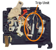
The trip unit's function is to activate the operating mechanism (open the circuit) in the event of the following overcurrent conditions: thermal overload, short-circuit currents (fault current), and ground fault.
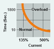
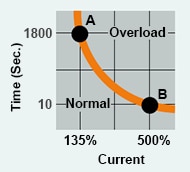
Thermal Overload: When this condition exists, a temperature buildup occurs between the insulation and the conductor. This is called a thermal overload. Eventually, this condition will result in a short circuit. Overload conditions are predictable if the current flowing into a conductor and its flow time is monitored. As a result, a time-current curve is used to indicate the boundary between the normal and overload conditions.
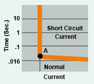
Short-circuit Currents: Short-circuit currents (fault currents) usually occur with abnormally high current flow due to the failure of conductor insulation. When the insulation between phases breaks down, short-circuit currents can be expected to flow into the fault (i). A typical time-current curve for a short circuit (instantaneous) element of a circuit breaker indicates that a trip will not occur until the fault current reaches or exceeds Point A in the curve (ii).
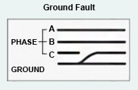
Ground Fault: A ground fault is a particular type of short-circuit current fault. It is a short circuit between one phase and the ground.
- 5.4 Electromechanical Trip Unit
Electromechanical trip units are integrally mounted in the circuit breaker. Thermal-magnetic trip units act to protect the conductors, safeguarding the equipment under high ambient conditions and permitting higher safe-loading under low ambient conditions. They are commonly used in low voltage circuit breakers.
An electromechanical trip unit utilizes temperature sensitive bimetals and electromagnets to provide overload and short-circuit protection. This is why the circuit breaker is referred to as "thermal-magnetic."
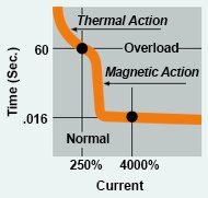
The thermal trip portion is used for overload protection. Its action is achieved using a bimetal that's heated by the load current. On a sustained overload, the bimetal will deflect, causing the operating mechanism to trip. Deflection is predictable and is a function of current and time. For example, a typical 100A breaker might trip in 1,800 seconds at 135% of rating (Point A), or 10 seconds at 500% of rating (Point B).
The magnetic trip portion is used for short-circuit (instantaneous) protection. Its action is achieved with an electromagnet, whose winding is in series with the load current. When a short circuit occurs, the current passing through the conductor causes the electromagnet's magnetic field to rapidly increase, attracting the armature coil and causing the circuit breaker to trip.
The combination of thermal and magnetic actions protects against overloads and short circuits. Please note the difference in the time-current curve. The thermal-magnetic trip unit is suited for most general-purpose applications because it is temperature sensitive, harmonics-insensitive and tends to automatically follow safe cable and equipment loading that varies with ambient temperatures.
- 5.5 Electronic Trip Units
Electronic trip units are integrally mounted on low voltage circuit breakers. Modern electronic trip units are offered with a variety of optional features and capabilities for specific power distribution system applications, such as increased accuracy, repeatability and discrimination. They also have built-in ground fault circuit protection and other features, such as programming, monitoring, diagnostics, communication, system coordination and testing. They are temperature insensitive, yet are generally more expensive than electromechanical trip units.
- 5.6 Arc Extinguisher
An arc extinguisher is the component of a circuit breaker that extinguishes an arc when the contacts are opened. An arc extinguisher (also called an arc chute) is a series of contacts that confine, divide and gradually open, making the arc easier to extinguish. Many low voltage circuit breakers use the DE-ION arc extinguisher. When the circuit is opened due to a fault condition, the arc is magnetically blown into the DE-ION
’s stack of insulated copper plates, giving the effect of a large number of short arcs in series. Each arc is quickly deionized when the current drops to zero in the alternating current cycle, and thus prevents the arc from restriking (see Current Zero Method).
- 5.7 Electrical Contacts
Electrical contacts in a circuit breaker are the interface that provides a continuous electrical connection between the power source and the power conductors of an electrical or electronic device. Every circuit breaker has a contact set containing a fixed and movable contact. When designing the contact set of a circuit breaker, the following characteristics should be considered:
 Contact surface layer degradations
Contact Resistance: Contact resistance is the most important factor. By definition, it is the resistance across the contact zone: the interface between the two mated contacts. The value of this resistance determines the quality of a contact: the higher it is, the greater the quantity of heat released by the contact. If the contact temperature increases above the design limit, the contact will deteriorate; that is, it will soften, melt and ultimately fail. Electrical contacts with low resistance will have a limited temperature rise, low thermal heating and the promise of a long life. But maintaining low contact resistance depends in large part on contact pressure and the type of contact material.
Contact Pressure: Contact pressure not only provides the initial insertion force to mate the contact members, but also the frictional force for both, holding the mated contacts together and compensating for manufacturing variations that can lead to loose or tight contact mating. Low or inconsistent contact pressure increases contact resistance, with the aforementioned results.
| Contact Material | Contact Resistance | |
| New | Oxidized | |
| Pure Silver | 6 μΩ | 25 μΩ |
| Gold | 31 μΩ | 31 μΩ |
| Copper | 29 μΩ | 400 μΩ |
| Brass | 370 μΩ | 1,400 μΩ |
| Silver-nickel | 23 μΩ | 60 μΩ |
Source: Technical Training Manual,
Marechal Corporation
Contact Material: Contact material affects both contact resistance and arc resistance. Some materials have low contact resistance, such as silver and gold. But gold is expensive and silver does not have good mechanical endurance. Copper has good electrical conductivity but tarnishes and pits under an arc. Brass (copper and zinc alloy) is cost-effective and very easily machined. Yet brass is subject to frictional wear (fretting corrosion) and oxidizes at ambient temperature, which increases its contact resistance; it also has a significant contact resistance when new, since the zinc contained in it is a poor conductive material. Under an arc, brass pits, which allows in-depth oxidization. Silver-nickel (85% silver and 15% nickel) combines the low contact resistance of silver with the durable mechanical properties of nickel. Silver-nickel only welds at extremely high pressure and temperature, therefore it withstands electric arcs quite well. Manufacturers utilize contacts coated with durable non-corrosive alloys to prevent pitting, galling, sticking and welding. Designing circuit breaker contacts manufactured with quality alloys (e.g. silver or platinum) increases contact life and ensures low resistance when carrying a full-rated load.
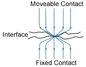
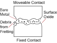
Contact Surface Layer: Contact resistance is influenced by the quality of the contact surface layer. Manufacturing variations and machining tolerances can create imperfections, such as roughness, waviness and unevenness in the contact surface layer not visible to the naked eye. Because of these imperfections, the true contact area is much smaller and more localized than the apparent contact surface area. Hence, current conduction at the contact interface is limited to very small contact spots or constrictions. Constriction resistance deviates the lines of current as they travel across these randomly located contact spots of the surface layer. In addition, surface films create layers of oxidation on the contact surface and introduce a film resistance that can increase the overall contact resistance.
On the microscopic level, all solid surfaces are rough, consisting of peaks and troughs, thus when contacts are mated, contact occurs at discrete spots. Constriction of the electric current by separate contact spots reduces the volume of material used for electrical conduction and increases electrical resistance. Source: Electrical Contacts: Principles and Applications, Second Edition.
Environmental Factors: Environmental factors can lead to the degradation of the contact surface layer, which causes changes in contact resistance and pressure. These factors include frictional wear, oxidation and fretting corrosion.
Frictional wear is the microscopic removal of material from one or both of the mated contact surfaces due to sliding or rolling during contact mating. It can also occur from vibrations, sudden impacts, temperature and moisture.
When micro-movements between contacts occur from mechanical vibrations, shock, or thermal cycling (expansion and contraction), which are all common in industrial environments, fretting corrosion is likely to occur. As the fretting process rubs away the protective coating of a contact surface and exposes the underlying contact metal, oxidation can occur with each movement. As oxides accumulate at the contact interface, fretting corrosion results, which can increase contact resistance and lead to possible contact failure.
Fretting corrosion is a combined wear and corrosion process in which material is removed from contacting surfaces when motion between the surfaces is restricted to very small amplitude oscillations. Oxidation is the most common element in the fretting process. In oxidized systems, fine metal particles removed by adhesive wear are oxidized and trapped between the fretting surfaces. The oxides are abrasive and increase the rate of material removal. Source: Corrosion: Understanding the Basics.
6. Types Back to Top
There are numerous types of circuit breakers, and the manner in which they are classified is just as varied. They can be classified by voltage class, phases/poles, installation/environment, enclosure construction, interrupting medium, tripping characteristics, and more. In this learning module, we will discuss the types of circuit breakers based on their voltage class. By means of voltage class, circuit breakers are broadly divided into three groups:
 High Voltage Circuit Breakers – ratings of greater than 72kV
 Medium Voltage Circuit Breakers – ratings between 1kV to 72kV
 Low Voltage Circuit Breakers – ratings of 1,000 volts or less
Given the fact that this learning module is being written for electronics design engineers who have a greater likelihood of working with the low voltage class, the focus of this discussion will be limited to low voltage circuit breakers. The low voltage class of circuit breakers is further divided into residential and industrial.
- 6.1 Residential Low Voltage Circuit Breakers
Both circuit breakers and fuses have been used to protect against the adverse effects of overcurrent conditions in residential installations. But circuit breakers are now the most employed type of overcurrent protection. Thermal-magnetic circuit breakers are often used for residential circuit breakers. Residential circuit breakers are typically 1-pole for 120V circuits or 2-pole for 240 volt circuits, rated at 15/20 amps, though they can go up to 50 amps. For the service entrance, circuit breakers can be rated up to 200 amps. Besides providing overcurrent protection, circuit breakers can also provide GFCI (ground fault circuit interrupters) protection. While thermal-magnetic circuit breakers are usually the most popular, arc fault circuit interrupters (AFCI) and ground fault current interrupters are also used in residential circuit protection.
A good example of a residential circuit breaker is the Type CH Circuit Breaker. It has a quick-make, quick-break switch mechanism, an inverse time element tripping operation, and a trip free handle design. A variation of this type is the CHF circuit breaker, which includes a trip flag to differentiate between a tripped condition and when the breaker is simply turned off. Due to its thermal-magnetic trip curve, it avoids nuisance tripping on mild overloads while reacting almost instantaneously to severe short circuit conditions.
Since high current arcing faults can occur from line to neutral or line to ground, arc fault circuit interrupters are increasingly installed in residential applications. The FIREGUARD AFCI Circuit Breaker is a branch feeder type that can mitigate high current arcing faults over the entire circuit, including connected cords.
The CHF type combination arc and ground fault circuit breakers not only mitigate high current arcing faults, they can also trip on overload, short circuit, low/high current arc, overvoltage, and ground fault.
Ground faults are electrical current leakage-to-ground, which can be a hazardous situation and creates a risk of shock or electrocution. To protect against ground faults, ground fault current interrupters (GFCIs) are often installed in residential installations. The Type CHF GFCI provides added safety over a standard electrical outlet in areas where shocks are more likely, such as kitchens, bathrooms, and workshops.
- 6.2 Industrial Low Voltage Circuit Breakers
Circuit breakers consist of varying frame sizes, spanning small circuit breakers that provide circuit protection for an individual residential home appliance (see previous section), to those in large switchgear designed to protect high voltage circuits supplying an entire metropolitan area. While high and medium voltage circuit breakers are beyond the scope of this learning module, low voltage circuit breakers (< 1,000 V) are used not only in residential applications, but also in commercial or industrial applications. The two common sub-categories of low voltage circuit breakers for commercial or industrial applications are:
 Miniature Circuit Breakers — rated up to 100 A
 Molded Case Circuit Breakers — rated up to 2,500 A
Industrial Miniature Circuit Breakers
Generally used in load centers, panelboards or control panels, industrial miniature circuit breakers are used to switch and protect low voltage circuits. Miniature circuit breakers are generally of the thermal or thermal-magnetic types. The primary types of miniature circuit breakers are Type B, Type C, and Type D, based on their tripping current. Type B trips between 3 and 5 times Full Load Amps (FLA); type C trips between 5 and 10 times FLA; and type D trips between 10 and 20 FLA. Miniature circuit breakers are commonly 2-, 3-, or 4-poled. They come in four mounting styles: DIN rail, Bolt-On, Plug-In, and Cable In/Cable-Out.

FAZ-D20/2-NA 2-Pole Thermal-Magnetic Circuit Breaker DIN rail
A very common industrial miniature circuit breaker is the FAZ-NA DIN rail type that's designed for use in branch service applications. The FAZ-NA is available with B, C, and D characteristics in accordance with UL 489, CSA
C22.2 No.5; UL 1077, CSA C22.2 No.235 and IEC 60947-2. They are used for feeder and branch circuit protection such as:
|
|
FAZ-NA circuit breakers are current limiting, which means they interrupt fault currents within one half cycle of the fault.
Bolt-on and Plug-in miniature circuit breakers are used in panelboards for easy installation and security. They are also switching duty rated for 120 VAC fluorescent light applications. They are available in 1-, 2-, and 3-poles, up to 100A. They are listed to UL 489 and are HACR rated.
- 6.3 Molded Case Circuit Breakers
Molded case circuit breakers provide circuit protection for machinery and electrical power distribution in commercial, industrial, mining, and military applications. They are used in equipment such as panelboards, switchboards, feed pillars, switchgear, motor control centers, control panels, combination starters, individual enclosures, and bus duct plug-in units, among others. Differentiated from miniature circuit breakers, molded case circuit breakers have a wider range of current ratings — up to 2,500 amps.
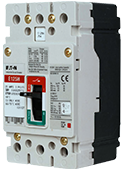
EGE3015FFG 3-Pole Thermal-Magnetic Circuit Breaker 415VAC 15A, G Series EG-Frame DIN rail Panel
A good example of a molded case circuit breaker is the Series G, which has current ratings ranging from 15A to 2500A with voltage ratings up to 690 VAC. They can be fitted with thermal-magnetic and electronic trip units, as well as residual ground fault and 30 mA earth leakage protection. What separates the Series G from other types of molded case circuit breakers is its space-saving footprint, averaging a 35% size reduction. The industrial breakers are available in current limiting versions with interrupting capacities up to 200 kA at 480 V without fuses in the same physical size as standard and high interrupting capacity breakers. The size reduction can be an important feature, as high-density control panels have become the norm. These breakers meet the requirements of UL, CSA
, IEC, CCC and CE.
For added circuit protection they possess a high speed "blow-open" action using the electromechanical forces produced by high-level fault currents. They also use a toggle-type mechanism that is mechanically trip free from the handle, so that the contacts cannot be held closed against short-circuit currents. Tripping due to overload or short circuits is clearly indicated by the position on the handle.
7. Codes and StandardsBack to Top
The electrical industry is required to ensure that circuit breaker design, manufacturing, testing and implementation are in compliance with specified regional codes and standards. Domestic and international standards and codes are established by organizations and associations including ANSI, CSA, IEC, IEEE, NEMA, NEC AND UL, to ensure electrical product safety and reliability, personal safety, and to mitigate the risks of equipment damage and fire.
*Trademark. Eaton is a trademark of Eaton Corp. Other logos, product and/or company names may be trademarks of their respective owners.
|
Test Your KnowledgeBack to Top
Are you ready to demonstrate your circuit breakers knowledge? Then take a quick 15 question multiple choice quiz to see how much you've learned from this Essentials Circuit Protection 1 Module.
To earn the Circuit Protection 1 badge, read through the module to learn all about circuit breakers, attain 100% in the quiz and give this page a star rating.


