 Energy Harvesting Electronics - Power 2
Energy Harvesting (also known as energy scavenging) is the process of capturing and converting small amounts of naturally occurring, ambient energy to power anything from small devices, such as sensors, microcontrollers, and wireless transceivers, to residential/commercial building systems. Energy harvesting systems extract and manage power from non-conventional power sources, such as acoustic, electromagnetic, electrostatic, fluidic, solar, thermoelectric, and vibrational energy. The energy captured can be used directly or stored for future use. In this learning module, we will first define these energy harvesting sources, and then take a closer look at photovoltaic systems, one of the most common types of energy harvesting systems, as well as discuss the circuitry used to produce, capture, and store energy, including some adjunct circuitry for power management and protection.
Related Components | Test Your Knowledge 
sponsored by
2. Objectives
Upon completion of this module, you will be able to:
- Identify the common and lesser-known types of energy harvesting technologies
- Describe the building blocks of energy-autarkic system design
- Discuss the operation of a Photovoltaic Energy Harvesting System, including the solar energy source, DC/DC Converters, MPPT Controller, and Energy Storage (Battery/Supercapacitor)
- Describe the typical devices used in Photovoltaic Electronics, such as photovoltaic cells/modules/arrays, semiconductor materials for PV cells, PV circuits, inverters, and power conditioning devices
3. Sources of Ambient Energy
There are many sources of environmental (or ambient) energy that can be harvested for use in a variety of applications, such as wireless sensor networks. In this section, let us overview the most common sources of ambient energy.
- Photovoltaic: Solar cells, also called photovoltaic (PV) cells, convert light directly into electrical energy. PV gets its name from the process of converting light (photons) to electricity (voltage), which is called the PV effect.
- Piezoelectric: The Piezoelectric Effect is the ability of certain materials to generate an electric charge in response to applied mechanical stress. The word piezoelectric is derived from the Greek piezein, which means to squeeze or press, and piezo, which is Greek for “push.”
- Electromagnetic: Electromagnetic (EM) radiation is energy that’s propagated through free space or a material medium in the form of electromagnetic waves, such as radio waves, visible light, and gamma rays. EM energy can be harvested from radio and television transmitters, cell phone networks, and satellite communications systems in small amounts to power small devices such as sensors, or even to perform wireless battery charging.
- Electrostatic: Electrostatic energy results from the electrostatic forces of kinetic motion, especially mechanical vibrations. This energy is converted into electrical energy by means of piezoelectric material, magnet coils, or vibration-dependent capacitors, to name a few.
- Thermoelectric: Based on the thermoelectric effect that was theorized by Thomas Seebeck (1821) and Jean Peltier (1834), thermoelectric energy is the direct conversion of temperature differences to electric voltage and vice versa. Thermoelectric energy generators produce a voltage proportional to the temperature difference between the two junctions of metallic conductors.
- Acoustic: Acoustic energy is sourced from external audible or noise forces. Acoustic energy harvesters capture, process, and store this energy for use in a variety of applications. The traditional way to harvest acoustic energy has been with the use of a Helmholtz resonator (EMHR); the conversion of acoustic energy into electrical energy is achieved via piezoelectric transduction in the diaphragm of the EMHR. More recently, acoustic energy harvesters have been developed that employ a silicon-micromachined piezoelectric-composite diaphragm for electroacoustic transduction.
- Fluidic: This type of energy has traditionally been harvested by turbine-based devices using rotating blades, but innovations in harvesting fluidic energy have expanded the possibilities of this type of energy source. One technique has been to submerge a flapping foil connected to an energy harvesting mechanism to extract energy from movements of underwater flows. Another method has been with the use of piezoelectric fluidic energy harvesters, which consist of a cylinder attached to the free end of a cantilevered beam that’s partially covered by piezoelectric patches. When fluid flow occurs, the cylinder is subjected to oscillatory forces, causing the beam to deflect, straining the patches, and producing electrical energy proportional to the forces.
4. Introduction To Energy-Autarkic System Design
Imagine for a moment that a piezoelectric transducer has been built into your shoe. When you walk, your kinetic motion is converted into electrical energy, which in turn powers an embedded system that measures force or counts your steps! Don’t imagine too long: inventions such as this one are being built now, targeting medical uses.
As illustrated in the previous example, the ability to power electronic systems with ambient energy has increasingly become a pursuit in the electronic engineering design community. Energy-autarkic or self-powered circuits supply power to circuit components where other forms of power would not wholly suffice. In this section, we will introduce the concept of energy-autarkic system design.
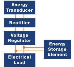
Figure 1: Block Diagram of an Energy-Autarkic System
Energy-autarkic systems that use energy harvesting are composed of several building blocks (Figure 1), which include:
- Energy transducers
- Rectifiers
- Storage Devices
- Voltage Regulators
- Loads
The energy transducer converts ambient energy into electrical energy. A rectifier is required in those systems where the transducer produces an AC voltage. A voltage regulator modifies (i.e., steps up or down) the nominal output voltage to a level that’s required by the load. The energy storage device (often a supercapacitor or battery) stores the energy which can then be utilized to power the load when necessary. Energy storage devices are needed due to (a) the discontinuous nature of ambient energy, (b) pulsed current during load transmission bursts and (c) the inability of supplying large currents due to the resistance of some transducers (i.e., voltage drop). Finally, the load is the device being powered by the system; it is generally small, since most energy harvesting systems supply power in the range of 1µW/cm3 to 100 mW/cm3.
- 4.1 Design Goals
The purpose of using energy harvesting to self-power devices is to increase the lifetime of remotely-located products or portable devices. It also assists in the on-site charging of rechargeable batteries and traditional/supercapacitors. There are generally two goals in designing energy-autarkic devices:
- Select very low-power electronics
- Harvest energy and store it efficiently
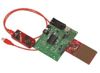
Microchip DV164133 Energy Harvesting Development Kit 16-Bit PIC MCU
One of the key design goals required by energy harvesting systems is the selection of very low power electronics. Microchip’s eXtreme Low Power PIC Microcontrollers with XLP Technology enables sleep-currents down to 9 nA and run-currents down to 30 μA/MHz. They offer very low power sleep modes with flexible wake-up sources that can extend battery life to over 20 years. The Microchip DV164133 (pictured left) contains solar cells and an XLP PIC microcontroller to facilitate developing energy harvesting applications. It is based on PIC MCUs with XLP technology and cymbet's EVAL-08 solar energy harvester. The development board features integral temperature sensors, data EEPROM, potentiometer, watch crystal, LEDs and expansion connector for PICtail modules. Supported PICtail module options include RF, SD/MMC Cards and more. The harvester features a high efficiency solar panel suitable for use with indoor or outdoor light. The harvester captures, manages and stores energy in two Cymbet EnerChip thin film rechargeable energy storage devices. The EnerChips supply energy to the development board when light is not available. Power condition and capacity are monitored by the PIC24F using energy conscious software algorithms developed by and Cymbet.
5. Photovoltaic Energy Harvesting Systems
Photovoltaic (PV) systems are perhaps the most common type of energy harvesting systems in use today. This type of energy harvester has grown in popularity over the last several decades. According to the Solar Energy Industries Association, the U.S. installed 2,387 megawatts (MW) of solar PV in Q2 2017, reaching 47.1 gigawatts (GW) of total installed capacity, which is enough to power 9.1 million American homes. Moreover, the use of solar-powered devices to power or supplement battery power for wireless sensor networks in industrial IoT systems is currently an area of wide interest and development. In this section, will we examine this technology by reviewing the common types of PV systems, as well as the typical components of such systems.
In general, Photovoltaic (PV) systems can be divided into four categories:
- Direct-coupled PV Systems
- Stand-alone PV Systems
- Grid-connected PV Systems
- Hybrid-connected Systems
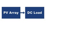
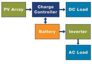
Direct-coupled PV systems have a PV array that’s directly connected to the load. Therefore, the load can operate only when the sunlight is available. Stand-alone PV systems are used in areas that are not easily accessible or have no access to an electrical power grid. Stand-alone PV systems are not connected to the power grid, and the energy produced by these systems is stored in batteries. Grid-connected PV systems produce electricity from panels that are either used immediately or directly fed into the grid, and are considered to be an infinite source or sink of power. Hybrid PV systems include at least one other source of power, other than PV, to meet the electrical power demand of the loads.
 |
 |
| Direct Couple | Stand-alone |
 |
 |
| Grid Connect | Hybrid |
Figure 2: Types of PV Systems
- 5.1 Photovoltaic Cell Operation
A solar/PV cell is formed by fabricating a p-n junction in a thin wafer of semiconductor material. Photovoltaic devices are usually made using silicon, although the current technology utilized is in a state of evolution (See section 6.1).
PV cells depend on the photovoltaic effect for converting solar radiation into electricity. The energy conversion is accomplished through the process of absorbing a photon and causing an electron to be excited from a lower state to a higher, less-tightly bound state in the PV material’s atoms. As a result, a hole occurs in the lower state, creating an electron-hole pair, where the electron moves to the top electrode of the cell (see Figure 3), while the hole moves to the bottom electrode. This creates a potential difference (voltage). When a load is connected, current flows.

Figure 3: Photovoltaic Device
- 5.2 Photovoltaic System
Similar to the energy-autarkic system described in Section 4, the main elements in a PV energy harvesting system include:
- Solar Energy Sources
- Energy Harvesting/Power Management ICs
- Energy Storage - Batteries/Supercapacitors
Solar Energy Source: Solar energy is radiant light and heat from the Sun that is harnessed using a range of ever-evolving technologies, such as solar heating, photovoltaics, solar thermal energy, solar architecture, and artificial photosynthesis. It is an important source of renewable energy, and its technologies are broadly characterized as either passive solar or active solar, depending on how they capture and distribute solar energy or convert it into solar power. Active solar techniques include the use of photovoltaic systems, concentrated solar power, and solar water heating to harness the energy. Passive solar techniques include orienting a building to the Sun, selecting materials with favorable thermal mass or light-dispersing properties, and designing spaces that naturally circulate air.
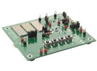
Maxim Integrated EV Kit
Energy Harvesting/Power Management ICs: Energy harvesting power management ICs serve several functions, including (a) capturing the energy from the transducer, (b) converting the converted energy to the appropriate regulation voltages, and (c) charging energy storage devices (i.e, batteries and/or supercapacitors). Another important function of power management ICs is the realization of maximum power-point tracking (MPPT), which is commonly used with photovoltaic (PV) solar systems to maximize power extraction (See Section 6.4).
Evaluation kits make the development of energy harvesting applications convenient. Maxim’s Energy Harvesting Charger EV kit helps a designer to quickly understand the low-power charging of micro-energy storage cells with ambient light. The EV kit has three solar cells, which charge a solid-state, thin-film battery (micro energy storage device); a boost controller is used to regulate and charge the on-board energy storage cell.
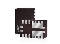
Silego GreenPak Configurable Mixed Signal IC
Along with energy harvesting PMICs, the use of configurable mixed-signal ICs (CMICs) gives a designer a flexible device that can integrate many system functions while minimizing component count, board space, and power consumption. A good example of a CMIC for energy harvesting applications is Silego’s GreenPak Series.

Figure 4: Supercapacitor Charging Reference Design by Silego
To illustrate how the GreenPak CMIC can be used, Figure 4 shows a supercapacitor charging reference design. The design will charge the supercapacitor up to a voltage determined by an Analog Comparator inside the GreenPAK, and then discharge the supercapacitor when VIN drops below a set voltage. If desired, the GreenPAK can also receive a Charge_EN signal which would allow a host controller to determine when it wants to begin charging the supercapacitor.
Energy Storage - Batteries: Energy storage is a means of storing energy for later use. A rechargeable battery is comprised of one or more electrochemical cells. It’s also known as a ‘secondary cell’ because its electrochemical reactions are electrically reversible. Rechargeable batteries come in many different shapes and sizes, ranging from button cells to megawatt grid systems. Rechargeable batteries have lower total cost of use and environmental impact than non-rechargeable (disposable) batteries. Some rechargeable battery types are available in the same form factors as disposables. Rechargeable batteries have higher initial cost, but can be recharged very cheaply and used many times.
Lead acid batteries hold the largest market share of electric storage products, but Nickel–metal hydride (NiMH) batteries are now a mainstay for consumer and industrial type of energy storage devices. Nickel–cadmium battery (NiCd) were invented in 1899, but have had limitations in their use due to the toxicity of cadmium; NiCd batteries have been almost completely replaced by nickel–metal hydride (NiMH) batteries. Lithium-ion batteries are commonly used in many consumer electronics; they have one of the best energy-to-mass ratios and a very slow self-discharge when not in use. Lithium-ion polymer batteries are lightweight and can be made in any shape desired.
Energy Storage - Supercapacitors: Supercapacitors are also called electric double-layer capacitors (EDLC) or ultracapacitors. These are generic terms for a family of electrochemical capacitors that do not have conventional solid dielectrics. Capacitance is determined by two storage principles: double-layer capacitance, a non-Faradaic reaction where charges can only be physically absorbed into the double layer without any electron transfer, and pseudocapacitance, an electron charge-transfer (Faradaic reaction) between electrolyte and electrode via electrosorption and surface redox processes. Supercapacitors support a broad spectrum of applications, including:
- Storage device for energy harvesting
- Backup power for industrial PCs and industrial controls
- Low supply current for memory backup in static random-access memory (SRAM)
- Power backup for memory controllers, flash backup, RAID systems, SRAM, DRAM
- Burst power support for flash lights and wireless transmitters
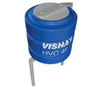
Vishay Hybrid Storage 196 HVC ENYCAP Capacitor
Supercapacitors bridge the gap between conventional capacitors and rechargeable batteries. They store the most energy per unit volume or mass (energy density) among capacitors. They support up to 10,000 farads/1.2 volt, up to 10,000 times that of electrolytic capacitors.
While supercapacitors have specific energy and energy densities that are approximately 10% of batteries, their power density is generally 10 to 100 times greater. This results in much shorter charge/discharge cycles. Additionally, they will tolerate many more charge and discharge cycles than batteries. Vishay’s Hybrid Energy Storage Capacitors with high capacity and energy density are an example of an energy harvesting storage device.
- 5.3 Harvested Power Dependencies
The amount of harvested power that can be converted into usable energy depends on many factors, including input vibration characteristics, the mass of the generator, natural frequency, the electrical load, mechanical damping ratio, and the electromechanical coupling coefficient of the system. For example, let’s consider the electrical load for a moment. The load affects the performance of circuits with respect to output voltages or currents, such as in sensors, voltage sources, and amplifiers. Adequate load impedance matching between the energy source, the transducer, and the electrical load is critical to ensure maximum power extraction of the harvested energy. This usually requires the use of power conditioning or interface circuitry to accomplish.
- 5.4 Other Energy Harvesting Systems Components
To complete an energy harvesting power application, especially for large PV systems or solar plants, additional components may be required, such as memory, actuators, communication interface, alarm and monitoring, charge controllers, sensors, combiner boxes, processing and control devices, DC/AC disconnects, cabling, and connection hardware (Figure 5).
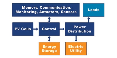
Figure 5: Block Diagram of Large PV System
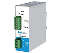
Bel Power Solutions DIN Rail Switching Power Supplies
For PV systems that require power monitoring, alarm circuitry, or other forms of power, AC/DC power supplies such as Bel Power Solutions’ DIN Rail Switching Power Supplies will often be utilized. These single phase power supplies have the added benefit of active power factor correction and easy DIN rail mounting.
6. Photovoltaic Electronics
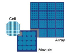
Figure 6: Photovoltaic Cells/Modules/Arrays
The basic element of a PV System is the photovoltaic (PV) cell. PV cells convert sunlight directly into electricity. To increase their utility, a number of individual PV cells can be interconnected together in a sealed, weatherproof package called a Module. To achieve a desired voltage and current, modules are wired in series and parallel into PV Arrays (Figure 6).
- 6.1 Semiconductor Materials for PV Cells
There are a number of types of semiconductor materials used in the conversion of sunlight to electricity. Materials range from crystalline and amorphous silicon to cadmium telluride, copper indium gallium sulfide selenides, dye sensitized solar cells, organic solar cells, and environmentally friendly copper zinc tin sulfide selenides (Table 1).
Solar cells are classified into first, second, and third generation cells, based in large part on the materials used. First generation cells—also called conventional, traditional, or wafer-based cells—are made of crystalline silicon, the commercially predominant PV technology, which includes materials such as polysilicon and monocrystalline silicon.
Second generation cells are thin film solar cells that include amorphous silicon, cadmium telluride, and copper indium gallium selenide cells and are commercially significant in utility-scale photovoltaics, power stations, building system integrated photovoltaics, or in small stand-alone power systems.
Third generation solar cells include a number of thin-film technologies often described as emerging photovoltaics—most of them have not yet been commercially applied and are still in the research or development phase. Many use organic materials, often organometallic compounds as well as inorganic substances. Despite the fact that their efficiencies have been low and the stability of the absorber material has often been too short for commercial applications, there is a lot of research invested into these technologies as they promise to achieve the goal of producing low-cost, high-efficiency solar cells.
Table 1: Comparison of PV Cell Generations
- 6.2 Single-Diode and Dual Diode PV Models
Single and double diode PV models have been widely used for modelling the output characteristic of a PV module. The single diode model is the simplest as it has a current source in parallel to a diode. Despite its simplicity, it exhibits acute deficiencies when exposed to temperature deviations. Moreover, its precision declines at low irradiance. The dual diode model has extra degrees of freedom, resulting in improved accuracy, but it has greater complexity. The series and parallel resistances in Figure 7 represent losses.
 |
 |
| Single Diode PV Model | Dual Diode PV Model |
Figure: 7 Equivalency Circuits for Single- and Dual-Diode PV Models
- 6.3 Inverters: Boost, Bidirectional
In general, energy systems based on photovoltaics require regulation due to the variability and discontinuity of the power being harvested. In many applications, PV systems must be supported with an additional energy storage unit to achieve a high-quality power supply. When such systems are used to power AC loads, or when the systems need to be connected to the electricity grid, an inversion stage is also required.
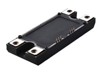
ROHM SiC Power Modules
A bidirectional converter is a power electronics based circuit configuration that can perform the stepping up and stepping down of voltage level with the ability of power flow control in both directions. Bidirectional converters can be used in various applications, including Uninterrupted Power Supplies (UPS), Energy Storage System (batteries and fuel cell), Vehicle to Grid (V2G), and Hybrid Grids with Renewable Energy Resources.
ROHM SiC Power Modules are used in photovoltaic and other renewable inverter converters for their low surge and switching losses, high-speed switching, and reduced temperature dependence. This power module is a half bridge module consisting of SiC double Diffused Metal-Oxide Semi-conductor (SiC-DMOS) and SiC Schottky Barrier Diode (SiC-SBD).
- 6.4 Maximum Power Point Tracking
Maximum power point tracking (MPPT) is a technique commonly used with photovoltaic (PV) solar systems to maximize power extraction at different light levels. Regardless of the ultimate destination of the solar power, though, the central problem addressed by MPPT is that of the efficiency of power transfer from the solar cell, which depends on both the amount of sunlight falling on the solar panels and the electrical characteristics of the load.
Solar cells have a complex relationship between temperature and total resistance that produces a non-linear output efficiency which can be analyzed based on the I-V curve (Figure 8).
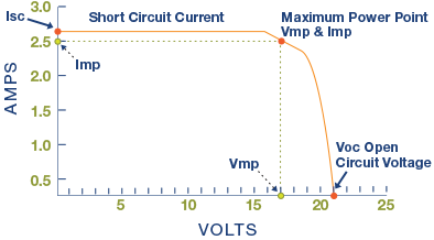
Figure 8: Example of PV Mocule I-V Curve.
A PV module’s behavior is summarized in an I-V curve. The I-V curve illustrates the difference between the voltage applied across a module, and the current delivered at that voltage. Each module’s I-V curve has a point that maximizes the power from the module.
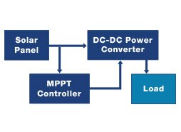
Figure 9: Integration of MPPT in Power Converter
It is the purpose of the MPPT system to sample the output of the PV cells and apply the proper load to obtain maximum power for any given ambient conditions. MPPT devices are typically integrated into an electric power converter system that provides voltage or current conversion, filtering, and regulation for driving various loads, including power grids, batteries, or motors (Figure 9). The power at the MPP (Pmpp) is the product of the MPP voltage (Vmpp) and MPP current (Impp).
When a load is directly connected to the solar panel, the operating point of the panel will rarely be at peak power. The impedance seen by the panel derives the operating point of the solar panel. Thus, by varying the impedance seen by the panel, the operating point can be moved towards the peak-power point. Since panels are DC devices, DC-DC converters must be utilized to transform the impedance of one circuit (source) to the other circuit (load). Changing the duty ratio of the DC-DC converter will result in an impedance change as seen by the panel. At a particular impedance (or duty ratio), the operating point will be at the peak power transfer point.
MPPT implementations utilize algorithms that frequently sample panel voltages and currents, and then adjust the duty ratio as needed. Microcontrollers are employed to implement the algorithms. Modern implementations often utilize larger computers for analytics and load forecasting.
- 6.5 Power Conditioning

Figure 10: Grid-Connected PV System
The introduction of variable renewables, storage, and microgrids into an electrical grid requires the conversion of electric power from one form to another (AC to/from DC and/or conversion between different voltage levels), and requires conditioning the power quality to what is needed by the subsystems being integrated. These functions are performed by Power Conditioning Systems (PCSs), which are a key to utilizing renewables, storage, and microgrids on a large scale.
Power conditioning systems also include system monitoring devices and isolation switches that can isolate the solar energy facility from the bulk electricity grid during off-normal conditions that could jeopardize or damage either the facility or the grid.
A grid-interconnected Photovoltaic (PV) illustrates the process of power conditioning the harvested power. The power converter of a PV system consists of Maximum Power Point Tracking (MPPT), DC/AC power converter, grid synchronization, and active/reactive power control.
The PV system has a passive input capacitive filter, which decouples the input voltage and current from the later power stages by reducing current and voltage ripples at the PV cell side. The input capacitive filter circuit, after filtering the ripple is fed to a DC/DC boost converter, where the MPPT function is performed. Galvanic isolation is also used when DC/DC converters with high frequency transformers are applied.
A DC/DC chopper block is connected through a DC link to a grid-tied DC/AC central inverter, which is connected to the grid through an output filter. The AC side filter provides harmonic mitigation and assists the converter–grid interface control. A low frequency transformer is used to increase the voltage and give isolation to the circuit (Figure 10).
*Trademark. Avnet is a trademark of Avnet Inc. Other logos, product and/or company names may be trademarks of their respective owners.

Test Your Knowledge
Power Skills 2

Are you ready to demonstrate your Power Essentials Energy Harvesting Electronics knowledge? Then take a quick 15 question multiple choice quiz to see how much you've learned from this Essentials of Power 2 Module.
To earn the Power Essentials 2 Badge, read through the module to learn all about Energy Harvesting Electronics, attain 100% in the quiz.

