A variable frequency drive (VFD) controls the voltage and frequency supplied to an AC induction motor in order to control and vary the motor's speed or torque. The common use of VFDs has allowed improved matching of loads to drives, precision control of motor speed or torque, and remote control of production-wide process systems that was not possible with mechanical or hydraulic drive methods of the now distant past. VFDs not only provide an electronic means of controlling motors, they also provide soft start capabilities, and offer the desirable benefits of energy savings and efficiency. This Essentials learning module covers the fundamentals of variable frequency AC drives, including types, theory, operation, and applications.
Related Components | Test Your Knowledge
2. Objectives
Upon completion of this module, you will be able to:
- Discuss the operation of an AC induction motor
- Calculate the synchronous and actual speed of an AC induction motor
- Explain the operation of multi-speed, wound rotor, eddy current clutch drives, and Variable Voltage Inverters
- Discuss the theory and operation of a variable frequency PWM drive
- Explain the difference between constant torque, variable torque, and constant horsepower loads
3. Review: AC Induction Motors
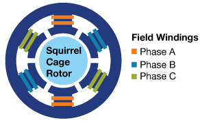
Figure 1A: Cross section view of a stator of a three-phase AC induction motor
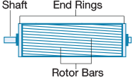
Figure 1B: Squirrel Cage Induction Motor Rotor
The stator of a three-phase AC induction motor has three sets of windings, spaced 120 electrical degrees apart, and energized by three-phase AC voltages, creating a rotating field of magnetic flux (Figure 1A).
The rotor of the motor is constructed in a squirrel cage configuration, consisting of pressed, slotted steel laminations. The rotor windings in a squirrel cage induction motor are aluminum or copper alloy bars that are placed in a skewed orientation to the motor's shaft and short circuited by end rings. Skewing the rotor bars reduces cogging, improves magnetic coupling between the rotor and stator, and can also improve starting torque (Figure 1B).
By mutual induction, current flows in the rotor bars due to the relative motion between it and the stator's rotating magnetic field. This generates torque, which causes the rotor and the output shaft connected to the load to rotate.
The rotor turns slightly slower than the synchronous speed of the stator's rotating magnetic field. If the rotor were to rotate at the same speed as the stator's magnetic field, there would be no relative motion between the rotor and the magnetic field, and no torque would be produced. The amount of speed by which the rotor lags the rotating magnetic field is called the slip of the motor. The higher the slip, the more torque will be generated.
- 3.1 Speed Control of an AC Induction Motor
The synchronous speed of an AC induction motor is calculated with the following formula: 
As such, the speed of a motor at synchronous speed depends on the number of motor poles and the frequency of the applied AC supply. In other words, if the number of poles and the applied frequency remain constant, so will the motor's synchronous speed. Now remember, we are referring to synchronous speed, not the actual speed of the motor, which takes into account motor slip (i.e., Synchronous Speed - Slip = Actual Motor Speed).
How does changing the number of motor poles impact the motor speed, assuming the motor has been connected by a full-voltage, across-the-line starter? Let's compare a 2-pole and a 4-pole motor running at 50 Hz with 2% slip:
Example A: (120 * 50) /2 = 3,000 rpm - 60 rpm (slip) = 2940 rpm
Example B: (120 *50) /4 = 1,500 rpm - 30 rpm (slip) = 1470 rpm
In this example, we approximately halve the speed by doubling the poles. While the motor speed can be changed or varied by changing the number of poles, changing the number of poles cannot vary motor speed continuously or in small increments of rpm.
Now, let's examine how changing the frequency, while keeping the number of poles the same, impacts the speed.
Example A: (120 *50) /4 = 1,500 rpm - 30 rpm (slip) = 1,470 rpm
Example B: (120 *51) /4 = 1,530 rpm - 30.6 rpm (slip) = 1,499.4 rpm
Example C: (120 *52) /4 = 1,560 rpm - 31.2 rpm (slip) = 1,528.8 rpm
In this example, we have maintained the number of poles but varied the applied AC frequency in 1 Hz increments. The result is the ability to vary motor speed in minute increments (rpm). We will discuss how the control of these minute frequency changes is made possible in Section 5. But first, let's review in Section 4 how motor speed has been controlled and varied prior to the advent of variable frequency PWM drives.
4. Types of Variable Speed Drives
Variable frequency PWM drives are a fairly recent phenomenon, dating back to the 1980s, as a way to control motor speed or torque. There have been other ways prior to these VFDs to enable variable speed control. Probably the earliest way to achieve variable speed control was through mechanical means, including mechanical transmissions such as belt or chain drives, adjustable pulleys, reduction gearing, throttle valves, or vane pitch controls. The biggest (but not the only) disadvantage of mechanical drives was excessive energy consumption.
There have also been different electrical and magnetic controls used to vary motor speed as well. Let's overview some of these ways in this section to gain a technological and historical perspective.

Figure 2: Two-speed, two-winding, wye-connected motor
| Low Speed | Close contacts 1, 2 and 3; Open contacts 4, 5 and 6 |
| High Speed | Close contact 4, 5 and 6; Open contacts 1, 2 and 3 |
Multi-Speed Motors: Multi-speed motors are induction motors that employ pole changing to obtain different motor speeds. They are constructed with custom wound stators that are often larger than a single speed motor would be of the same horsepower rating to fit in the extra set of windings. Pole changing is done by connecting and disconnecting the respective sets of windings to achieve the speed change (See Figure 2). Multi-speed motors are appropriate when the application requires a limited number of operating speeds.
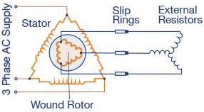
Figure 3: Wound rotor motor control
Wound Motor Rotor Control: Wound rotor motors do not have a squirrel cage rotor, as in most AC induction motors used today. Rather, the rotor is wound with copper windings and connected to an external resistor circuit via slip rings on the motor shaft (See Figure 3). When the resistors are shorted out of the circuit, the motor behaves like a squirrel cage induction motor. However, when the external resistors are inserted into the circuit, motor slip can be increased or decreased to enable variable speed control. As expected, energy is dissipated in the resistors as heat, which is a source of wasted energy. Once popular, wound motor rotor control has been primarily replaced by VFDs.

Figure 4: Eddy Current Clutch
Eddy Current Clutches: Eddy current clutch drives were a reliable means of variable speed or torque control for a long time. They utilize a drive assembly, an SCR-based field coil controller, and a tachometer for feedback used by the closed-loop control system. The drive assembly is made up of (1) a constant speed AC motor called the drum assembly, (2) a variable speed output shaft called the rotor assembly, and (3) a field coil assembly, which is the eddy current coupling. When the controller outputs a DC voltage to the field coil and energizes it, magnetic fields are developed and flux flows in both the drum and rotor assemblies. Eddy currents are generated in the drum, which rotates at the same speed as the AC motor. As the magnetic fields surrounding the drum and rotor interact, the rotor is induced to turn (torque) in the same direction as the drum. This causes the output shaft to increase in speed. The controller can vary the voltage applied to the coil, which varies the slip between the drum and the rotor. The output shaft speed will always be slower than the constant speed drum because of the slip.
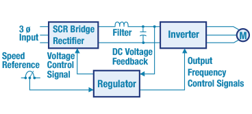
Figure 5A: Variable Voltage Source Six-Step Inverter
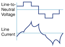
Figure 5B: Output Waveforms
Variable voltage source (6-step) inverters: While variable voltage inverters are considered VFDs, they use a different control architecture than the now popular PWM-based VFDs. They convert the AC input voltage into a variable DC voltage by means of a three-phase SCR converter. A DC-to-AC inverter takes each of the three-phase output lines and switches them from positive to negative for 180° of each 360° cycle (See Figure 5A). The phases are sequentially switched at 120° intervals, thus creating the six-step line-to-neutral voltage (See Figure 5B). An LC filter is utilized to produce a solid DC bus voltage. A voltage regulator is required to preset the DC bus voltage to the level needed to provide the required output voltage amplitude to the motor. Output frequency is controlled by a speed reference signal that sets the control logic to achieve the correct gate or base-drive signals for the semiconductors in the inverter section.
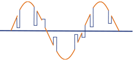
Figure 6: Voltage Notches of the AC input line
The installed population of Variable Voltage Six-Step inverters has steadily declined due to some undesirable condtions they exhibit; they are usually replaced with PWM drives. At low voltage and frequency, they have excessive harmonic currents, causing motor overheating, and can exhibit torque pulsations and/or cogging. The harmonic currents can place stresses on motor insulation and may require derating standard induction motors or using inverter-duty motors. Another problem with these devices is voltage notching of the AC input line (See Figure 6).
Voltage notching is distortion produced by the normal operation of SCRs when current is commutated from one phase to another, and during these periods there is a momentary short circuit between two phases. Three-phase SCR converters are the most common source of voltage notching. The severity of the notch is determined by the source inductance between the converter and the monitoring point. The width and depth of the notching depends on the output speed.
5. Variable Frequency PWM Drives
A variable frequency PWM drive controls the speed of an AC motor by varying the frequency of the applied AC supply. The drive also regulates the output voltage such that it remains proportional to the output frequency to ensure a constant volts per hertz ratio (V/Hz), in order to produce consistent torque throughout the speed range. VFDs use pulse width modulation (PWM) so motor speed and torque characteristics can be adjusted to match the load requirements.
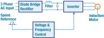
Figure 7A: Block Diagram of a variable frequency PWM drive
VFDs are divided into four sections: the AC-to-DC rectifier, DC link bus, DC-to-AC inverter, and the gate control circuit. A fixed diode front end bridge rectifier converts the AC input voltage to a pulsating DC bus voltage. The DC bus voltage is then filtered and applied to the inverter section. The DC link bus is where the pulsating DC is smoothed into pure DC voltage. The filtered DC bus consists of capacitors connected in parallel and a large inductor connected in series with the DC bus. The DC bus voltage is then converted back into AC in the inverter with electronic devices such as insulated gate bipolar transistors (IGBT) using Pulse Width Modulation (PWM).
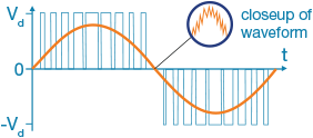
Figure 7B: Output PWM Voltage Waveform and Sinusoidal Current Waveform
In the PWM modulation method, the drive is controlled by employing positive pulses in one-half cycle, and negative pulses in another half cycle. In each group, the pulses differ in width. The pulses in each group have varying widths that correspond to varying voltage values. Lower pulse width represents lower voltage and higher pulse width represents higher voltage. The output voltage is turned on and off at a high carrier frequency, with the duration of on-time, or width of the pulse, controlled to approximate a sinusoidal current waveform. The fundamental output frequency is adjustable with the V/Hz ratio staying constant.
- 5.1 Volts per Hertz Ratio

Figure 8: Volts per Hertz Ratios
In order to maintain full torque throughout the entire speed range of the AC induction motor, a constant V/Hz ratio must be maintained. This essentially means that voltage and frequency must increase proportionally as motor speed increases or decreases. A variable frequency drive can maintain this ratio through several control methods:
- Scalar control: in this control mode, a fixed V/Hz ratio is maintained across the entire speed range. For a 460V motor running at 60Hz, the ratio would be 7.67. For 230V motor running at 60Hz, the ratio would be 3.83. There is an exception to this rule, however, at low speeds. At very low speeds, the motor windings appear more resistive than inductive. Thus, most VFDs will apply an amount of fixed voltage boost at zero rpm. As the motor ramps up, a proportion of fixed boost is replaced by the standard V/Hz ratio.
- Open loop flux vector control: in this control mode, speed is approximated mathematically in order to control the flux and torque produced. This type of control mode is also known as sensorless vector control.
- Closed loop flux vector control: in this control mode, speed is directly measured by an encoder in order to control the flux and torque. This type of control has the benefit of being able to provide a wide torque bandwidth, typically from 0 to 500 Hz.
- Direct torque control: in this control mode, there are both speed and torque control loops such that real speed and torque can be simultaneously monitored so the inverter can respond to the calculated error to ensure a very efficient means of control. This mode can maintain a 0.1 to 0.5 % of motor slip rating.
- Active Energy Control: utilizes an energy-optimizing algorithm to employ a dynamic V/Hz control method, in order to take into account the real-time operating parameters of the motor when determining the output voltage of the VFD. The control algorithm monitors the motor load and motor current, as well as other parameters, to find an operating point that both optimizes energy usage and assures motor stability (See Related Components for more information).
6. Starting Methods
Motor starting is a common activity of any motor drive application. The method by which motors are started can have a major impact on energy consumption, safety, and application requirements. There are three common methods of starting AC induction motors: full-voltage, reduced voltage, and soft starting (VFD). Let's go through examples of these methods in this section.
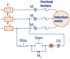
Figure 9: Full-Voltage, Across the Line, AC Motor Starter
Full-Voltage Starting Method: Full voltage starting employs a simple pushbutton and relay control. Figure 9 is an example of a Full Voltage, "across the line" motor starter. Pushing the start button energizes the M relay, which in turn closes the three M contacts and applies full input voltage to the induction motor. Fuses and heaters provide overcurrent and overload protection, respectively.
One of the problems of starting AC motors with full-voltage, across the line starters, is that the inrush current can draw at least 6 times the full load amp (FLA) rating of the motor during start up. This causes an increased demand on the electrical power system, while also being a source of wasted energy. Moreover, if a load were to require a slow start up speed, which can occur with high inertia loads, this type of motor starter would be inappropriate.
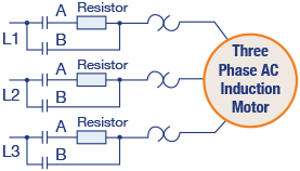
Figure 10: Reduced Voltage Starting: Primary Resistance Starter
Reduced-Voltage Starting: Instead of full-voltage motor starting, the reduced-voltage starting method can be utilized, which allows a motor to be started at a reduced voltage with lower start-up current. There are several types of reduced voltage starters. The common methods include: primary resistance, auto-transformer, wye-delta, and partial winding. Figure 10 illustrates one type, a primary resistance starter. This type of starter has two control relays, A and B. To start the motor, Relay A is energized, closing the three A contacts, and applies input power through the resistors, which reduces the voltage at the motor terminals and limits starting current. As the motor accelerates, the current through the resistors decreases, reducing their voltage drop and increasing the voltage across the motor terminals. The resistance is disconnected when the motor reaches a desired speed. When the motor is brought up to the desired speed, relay A is deenergized and relay B is energized, thereby locking in the three B contacts and applying full voltage to the motor.
While starting current is limited and less wasteful energy is consumed, the motor has less torque during start up and increased slip. Greater slip reduces efficiency.
| Starter Type | Starting Current (% of FLA) |
|---|---|
| VFD | 100% |
| Wye-Delta Starter | 200-275% |
| Solid State Soft Starter | 200% |
| Autotransformer Starter | 400-500% |
| Part Winding Starter | 400-500% |
| Across the Line Starter | 600-800% |
Table 1: Comparing Starter Types and Inrush Currents
Soft-Starting: A VFD can overcome the problems associated with full- and reduced-voltage motor starters because of its inherent soft start capabilities. Unlike all other types of starters, the VFD can use frequency to limit the voltage and current delivered to the motor (See Table 1). Acceleration and deceleration ramps can be programmed into the VFD such that we can select the ramp times, just as long as they are compatible with the load inertia. What makes this possible is that VFDs maintain a constant V/Hz ratio and torque throughout the speed range of the motor.
7. Braking Methods
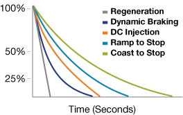
Figure 11: Comparison of Braking Methods
The method of stopping or braking a load is an important parameter when applying a VFD to a specific application. The braking method chosen will depend on the mass, inertia, and friction of the load or system. The basic ways of braking a load are:
- Coast to stop: removing power and permitting the load to coast to a stop
- Ramp to stop: VFD programmed deceleration time
- DC Injection stop: a small DC current is injected into the stator winding. This creates a stationary magnetic field in the air gap and assists in braking the motor.
Coasting and ramp braking are programmed when a VFD is configured. However, dynamic and regenerative braking require additional equipment (See Section 7.1).
- 7.1 Dynamic and Regenerative Braking
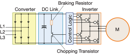
Figure 12: Braking Resistor Circuit
When an induction motor's rotor is rotating below synchronous speed, it is converting electrical energy into mechanical energy, and is in a motoring condition. But what happens in the event that the rotor turns faster than synchronous speed? In such a case, the induction motor acts like a generator, converting mechanical energy into electrical energy. This condition is called regeneration.
An example of regeneration is when a VFD driving a fan attempts to lower the fan's speed by decreasing its frequency. But the fan's inertia will likely resist the change in speed, causing the motor to operate above the VFD's output frequency. This causes energy to flow from the load back through the motor and into the VFD. This regenerative energy will cause a buildup of energy in the DC bus capacitors, increasing the bus voltage. If this increased voltage is not bled off, VFD components could be damaged if the voltage exceeds their design characteristics.
By routing the excess DC current through a braking resistor bank, however, the excess voltage can be dissipated in the form of heat energy that is released into the atmosphere typically by convection. This is called dynamic braking.
An alternate way of dissipating regenerative energy is to feed the energy back into the input supply grid; this method is called regenerative braking. This requires the VFD to be fitted with a regenerative braking circuit where forward and reverse IGBT bridges are used to dissipate regenerative electrical energy and feed it back into the input supply.
8. Applications
Variable frequency drive systems offer many benefits including energy savings through improved energy efficiency. The energy savings are obtained by eliminating throttle, operational, and friction losses that are characteristic of mechanical or electromagnetic variable speed drives. VFD applications are load-type dependent. So let's discuss the three types of loads: Constant Torque, Variable Torque, and Constant Horsepower Loads.

Figure 13: Constant Torque Loads
Constant Torque Loads: A constant torque application is when the torque is constant across the entire speed range of the motor drive system.
The relationship of horsepower, speed, and torque is given by the following formula:

As such, with torque being constant, horsepower and speed vary proportionally with each other. Constant torque loads are used in conveyors, positive displacement pumps, extruders, and high inertia loads.
Constant Horsepower Loads: A constant horsepower application is when the torque varies inversely with speed. They have high torque at low speeds and low torque at high speeds.Thus, when the torque increases, the speed decreases in order to have a constant horsepower load. This is described in the following formula:
Power (kW) = RPM • Torque (ft-lb)/3917
An example of a constant horsepower load would be a lathe, drilling, or milling machine where heavy cuts are made at low speed and light cuts are made at high speed.
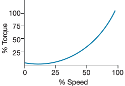
Figure 15: Variable Torque Loads
Variable Torque Loads: In a variable torque load of a motor drive application, much less torque is needed at low speeds than high speeds. The torque varies directly with the speed squared:
T = kN2
Where, T = torque (Nm or lbf ft), k = constant and N = pump speed in RPM
Moreover, variable torque applications can leverage a lot of energy-savings since power varies with the speed cubed:

For example, at half speed (50%), the power required is only one eighth of the rated maximum. VFDs are often used in pumping applications such as centrifugal fans, blowers, air handlers or compressors, because of the energy savings that can be obtained.
9. Energy Efficiency
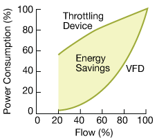
Figure 16: Energy Saved by Using a VFD to Control Flow
In the early days of variable frequency drive technology, the typical application was in process control for the manufacturing of synthetic fiber, steel bars, and aluminum foil. Because VFDs improved process performance and reduced maintenance costs, they replaced motor generator sets and DC motor drives. When the energy crisis occurred in the early 1970s, saving energy became a critical goal, and the use of VFDs quickly spread into large pump applications and eventually into HVAC fan systems.
In many flow applications, a mechanical throttling device is used to limit flow. While this can be an effective means of control, it also wastes mechanical and electrical energy. If a throttling device is employed to control flow, energy usage is shown as the upper curve in Figure 16, while the lower curve demonstrates energy usage when using a VFD. Because a VFD alters the frequency of an AC induction motor, speed, flow, and energy consumption are reduced in the system.
| 1.6 | 12.5 | 25 | 42 | 50 | 75 | 100 | |
| 5 | 35 | 80 | 88 | 91 | 92 | 94 | 95 |
| 10 | 41 | 83 | 90 | 93 | 94 | 95 | 96 |
| 20 | 47 | 86 | 93 | 94 | 95 | 96 | 97 |
| 30 | 50 | 88 | 92 | 95 | 95 | 96 | 97 |
| 50 | 46 | 86 | 92 | 95 | 95 | 96 | 97 |
| 60 | 51 | 87 | 92 | 95 | 95 | 96 | 97 |
| 75 | 47 | 86 | 93 | 95 | 96 | 97 | 97 |
| 100 | 55 | 89 | 94 | 95 | 96 | 97 | 97 |
| 200 | 61 | 81 | 95 | 96 | 96 | 97 | 97 |
Table 2: VFD Efficiencies vs. Percent Load (Source: U.S. Department of Energy)
Beyond the energy that VFDs can save, they are also very efficient. Most can have efficiencies of more than 97% at full load. However, efficiency decreases at light loading. VFDs rated at 10 HP or above have over 90% efficiency for loads greater than 25% of full load (See Table 2).
*Trademark. Eaton is a trademark of Eaton Corp. Other logos, product and/or company names may be trademarks of their respective owners.
Shop our wide range of variable frequency drives, motor starters, manual motor controllers and other accessories. Shop Now
Test Your Knowledge
VF AC Drives

Are you ready to demonstrate your variable frequency AC drives knowledge? Then take a quick 15-question multiple choice quiz to see how much you've learned from this Variable Frequency AC Drives Learning Module.
To earn the Variable Frequency AC Drives Badge, read through the module to learn all about variable frequency AC drives, attain 100% in the quiz, and leave us some feedback in the comments section.


