There are several different methods that we can use to create the Programmable Logic design within an FPGA or heterogeneous SoC. The goal of this course on programming languages is to explore the different methods that can be used to capture a design.
Development Kits | Test Your Knowledge
2. Objectives
Upon completion of this module, you will be able to understand:
- The process of programmable logic creation
- The difference between Synthesizable and Non-Synthesizable code
- The history and basics of VHDL and Verilog
- The basics of HLS
- The role of a System Optimising Compiler and how it is used
- More about HDLs such as MyHDL and Chisel
- Higher level frameworks which allow the use of languages such as Python
3. Programmable Logic Creation
Before we jump too far into the languages themselves, we need to first understand the FPGA implementation process and how it is different from traditional software designed to run on a processor.
The main difference between the software and programmable logic implementations is that the software world is inherently sequential. To execute a software application, each instruction in the application must be fetched from memory, decoded, and then executed. Of course, computer architects implement pipelines, conditional execution, and multiple cores to increase performance.
Commonly used embedded system languages such as C and C++ are therefore designed to operate with this sequential execution in mind, although there are ways to code for multi-threading and parallel programming.
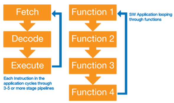
Figure 1: Software application execution
However, programmable logic is inherently parallel, and therefore the Hardware Description Languages used to capture design intent need to be able to support both parallel and sequential structures.
While implementation of software requires a single stage compilation, implementing an FPGA is a three-stage process which can be much more involved to achieve the desired performance. The input is the design described in a Hardware Description Language (HDL), while the output is the programming file.
- Synthesis – During the synthesis stage, the logical structures defined within the HDL are extracted. Synthesis therefore determines the logic design which will be implemented, and this includes logic gates, RAMS, DSPs, etc. Synthesis will analyze the design and perform logic optimization, trimming unused signals and variables. This can result in unwanted optimizations or synthesis decisions, and as such the developer can control synthesis behavior, strategies, and optimizations using synthesis constraints. Constraints are text based and guide the synthesis tool during its operation.
- Implementation – The implementation stage takes the netlist created by the synthesis tool and performs two separate functions. The first step in the implementation process is to map the logical functions defined by the synthesis netlist into logic resources available within the logic. To ensure the timing performance can be achieved, placement needs to be timing aware, to ensure logic functions are placed close together. Once all the logic resources have been placed, they need to be interconnected as defined in the synthesis netlist. This step is called routing, and it has a significant impact on the timing behavior of the logic implementation. Just as we can with synthesis, we can use constraints to control the behavior of the place and route solution.
- Bit File Generation – This is the final stage, and it takes the output from the implementations stage and creates a programming file which will configure the logic. Depending upon the target device, this may be used to program an SRAM, FLASH, or One Time Programmable FPGA.
4. Synthesizable vs Non-Synthesizable Commands & Structures
One of the key concepts that we need to understand when writing code for programmable logic implementation, regardless of the language, is the concept of synthesizable and non-synthesizable command and structures.
Synthesizable code is code for which the synthesis tool will be able to extract a logical structure. At the simplest level, this could be a logic gate or a flip flop. Synthesizable code consists of commands, which the synthesis tool can interpret and implement, along with specific coding structures which the Synthesis tool can interpret. As such, we find that for synthesizable code, we are constrained by not only the commands we can use, but also the way in which we use those commands.

Figure 2: VHDL Synthesisable Accumulator
Non-synthesizable code, on the other hand, is where the synthesis tool cannot work out and implement the design intent. A good example of this would be a delay or a statement to print out a message. Such functionality can be implemented within programmable logic, however, it requires the implementation of shift registers, timers, and state machines, the creation of which is beyond the capabilities of synthesis tools.
An example of non-synthesizable VHDL can be seen below which includes both a time delay (wait for 1µs) and reporting messages. The command structure has multiple waits; it should be noted that within the process VHDL also cannot be synthesized.
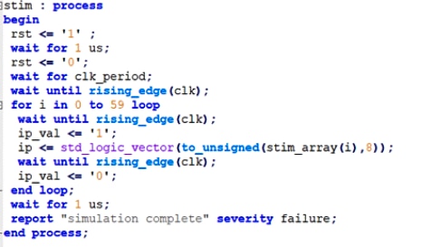
Figure 3: VHDL Example of Non-Synthesisable code
Both synthesizable and non-synthesizable code will be used in most programmable logic developments. Synthesizable code is used to describe the logic design, while the non-synthesizable code is used to create test benches which verify the behaviour.
5. VHDL
VHDL is one of the two main HDLs, the other being Verilog. VHDL actually stands for Very High-speed integrated circuit Hardware Description Language (VDHL); it was originally created in the 1980s by the US Department of Defense, who desired a standard language with which defense contractors could document and simulate their ASIC designs. Of course, it did not take long before the first synthesis tool was available to directly implement logic from VHDL descriptions.
The VHDL language itself was based on another DoD language, ADA, and when it was initially released VHDL fell under ITAR (International Traffic in Arms Regulations) controls. However, ITAR status was removed in 1986 when the language reference manual was passed to the IEEE for standardization. This led to the first of several IEEE versions of the VHDL, the first starting in 1987. This initial version was followed five years later by VHDL-1993, which was the first major revision and introduced multi value logic, useful when you want to define weak pull ups or tristate. VHDL-1993 is still the most commonly used version of the language today nearly 25 years later. Minor revisions of VHDL were introduced in 2000 and 2002, while a more major revision was introduced with VHDL 2008; however, many EDA tools suppliers are still yet to fully support this.
The basic VHDL file consists of two parts:
- Entity – This defines the inputs and outputs of the design. It is also possible to include customization parameters within an entity.
- Architecture – This defines the functionality of the module itself, and it’s where we implement the majority of the VHDL code.
Within the architecture, once the types, constants, and signals have been defined, every command is implemented concurrently. Most of the logic implemented within a VHDL file will be contained within a VHDL process. A process is a concurrent statement, meaning that all processes within the architecture are concurrent. However, within a process, the statements are executed sequentially; within simulation processes are awakened for execution by the sensitivity list.
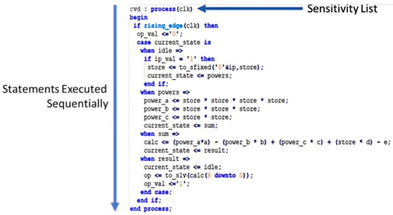
Figure 4: Process Implementing a State Machine
Communication between processes and combinatorial structures within an architecture uses signals. Signals can be declared to be one of several types, and the most common three types are:
- std_logic – Logical type which can be one of nine logic values (0,1,W,H,L,-,X,Z,U)
- Unsigned / Signed – Logical type capable of storing signed and unsigned numbers
- Integer – Integer type, and the range of the integer can be defined. However, if it is not defined, it defaults to 32-bit implementation
In comparison to Verilog, VHDL is very strongly typed; as such, conversion between types requires a conversion function. This can prevent some issues which may result from incorrect conversion between types accidentally.
While entities and architectures are the mainstay of the VHDL developments, we will also work with packages, functions, and procedures.
- Packages – Used to store common constants, functions, and procedures which can be used across several VHDL designs.
- Functions – Contain sequential statements which implement logical or mathematical functions. We can use functions to define conversion functions between types as well.
- Procedures – Contain collections of sequential statements.
- So, what is the difference between functions and procedures? To a newcomer, Functions and Procedures may seem very similar; however, there are several subtle but significant differences. The largest difference between the two is the number of returned parameter functions. Functions must return only one parameter, while procedures can return zero or multiple parameters.
6. Verilog
Unlike VHDL, which emerged from the US DoD, the other main language used for programmable logic development, Verilog, emerged from the commercial sector. Verilog emerged around the same time that VHDL did in 1983, being developed for a logic simulator offered by Gateway Design Automation (now Cadence).
As a language, Verilog is based upon C, Pascal, and OCAM. This makes Verilog much less verbose than VHDL, and unlike VHDL, Verilog is not strongly typed.
Like VHDL, Verilog was first standardized by the IEEE in 1995, and has undergone several revisions over the years, including 2001 and 2005. Verilog 2005 is also the base for System Verilog along with OpenVera and SuperLog. System Verilog includes many additional constructs and support for design modelling and verification. Since 2008, Verilog and System Verilog have been part of the same standard.
The basic element of Verilog is the module. The module is where we declare not only the inputs and outputs of the module, but also where the body of the design is implemented.
To implement sequential structures within Verilog we use the "always block". Like VHDL, the always block also has a sensitivity list which triggers the execution of the block. Within an always block commands are executed sequentially, while multiple always blocks operate in parallel.
Within a Module we can use either a wire or a reg to represent variables in the design. Which one we use depends upon if we are implementing combinatorial or sequential logic, and if we are implementing the code within an always block.
If we are performing a combinatorial assignment outside of an always block, all the variables can be declared as wires. However, if we are using an always block to implement either a combinatorial or clocked structure, then the Left-Hand Side variable must be declared of type Reg.
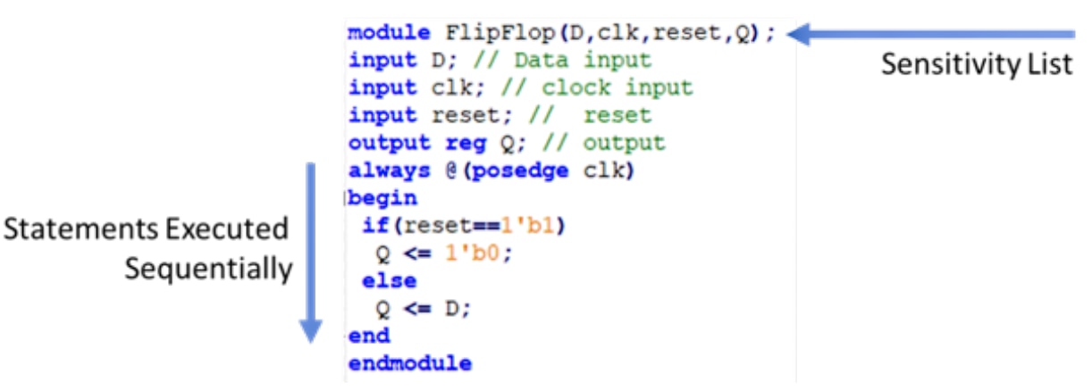
Figure 5: Verilog Always Block
Verilog also allows the developer to create and reuse code using tasks and functions.
- Tasks – Are like subroutines and contain code which implements the desired function. A task is called, receives its data, processes the data, and returns the results of the task. Tasks are defined within a module and can be located in separate files, which can be called using the ‘include option’ in the calling module.
- Functions – Are like tasks; however, they can only drive one output and cannot contain any delays, for example, waiting for clocks, etc.
7. VHDL & Verilog Language Wars
During the early 1990s, when both VHDL and Verilog were gaining in popularity, there occurred what is now called the language war. The VHDL / Verilog language war took place in the unlikely EDA battleground, as EDA tool vendors and engineers pushed one language over the other with the expectation that like the VHS / Betamax battle one would reign supreme. This would lead to many heated conversations on discussion boards and at conferences between engineers on the benefits of their chosen language.
As it turns out, the war ended in a truce when it was realized by EDA vendors that both languages where maturing and issues within the language reference manuals were being addressed by later revisions of the standards. Major advances in this were the IEEE 1993 version and the adoption of Verilog as an IEEE standard, also.
8. High Level Synthesis
High Level Synthesis (HLS) allows programmable logic developers to create IP cores using high level languages such as C, C++, or SystemC.
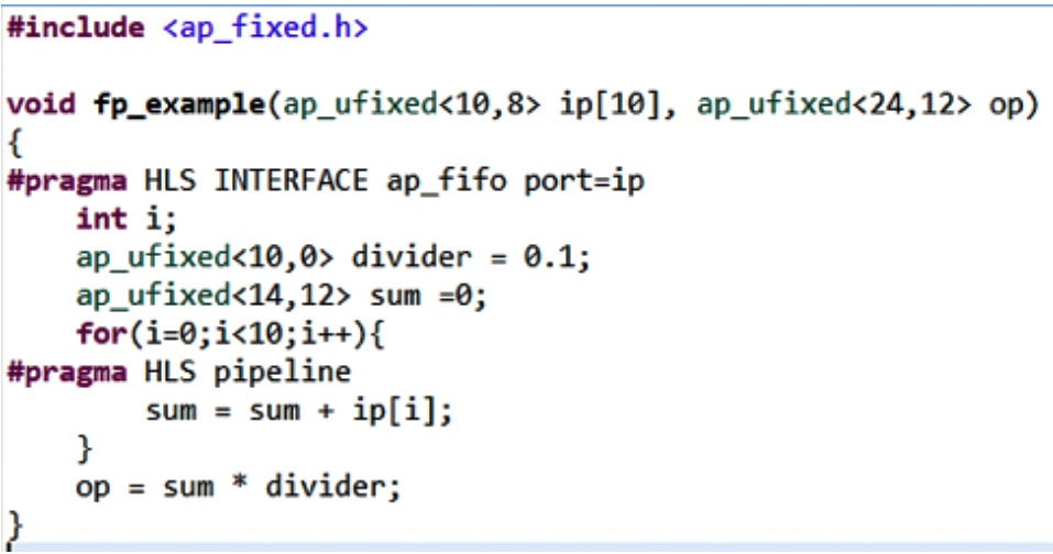
Figure 6: Example of HLS Code
As we can work at a higher level of abstraction using a C-based language, we can create more complex designs faster. This shortening of the design cycle comes in two areas. The first comes from the development of the algorithm at a higher level. However, perhaps the largest savings come across in the verification times scales, as we can simulate the design in C as well. This means we are not simulating at the clock cycle level but at the functional level, significantly accelerating the simulation time.
Of course, there is also a learning curve associated with learning a new language and approach such as HLS.
It should be pointed out at this time that the output from HLS is both VHDL and Verilog source code, which is then implemented following a traditional programmable logic flow.
HLS converts C into an HDL for implementation using three stages:
- Scheduling – In this phase, the HLS algorithm determines the order of operations and assigns them to a clock cycle.
- Binding – In the binding phase, the operations are bound to logic resources within the target FPGA device, e.g. DSP, Block RAM, or LUTs.
- Control Logic Extraction – In this final phase, the control logic is generated to control synthesized logic.
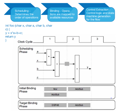
Figure 7: HLS converts C into an HDL for implementation using three stages
Free HLS Tools are generally specific to a vendor’s tool chain and devices. For the remainder of this section we use Xilinx Vivado HLS as the base example.
The standard development flow for an HLS based IP module is:
- Develop the algorithm in C, using the appropriate libraries
- Create a C Test Bench
- Update the algorithm until the functional performance is achieved
- Perform High Level Synthesis generating the HDL for implementation
- Perform Co-Simulation with RTL tested by C Test Bench
- Export the IP core into Vivado
To enable the maximum performance the synthesis tool needs to provide several libraries. For Vivado HLS this includes:
- Arbitrary Precision libraries – These allow operands which are not based on power of 2 (e.g., 8,16,32). These are especially important for fixed point mathematical operations.
- Video Libraries – Provides a range of image processing functions, which are synthesizable along with providing several functions that integrate with OpenCV for verification and simulation.
- Math Library – Provides a range of functions, like what we would find in math.
- Linear Algebra – Provides libraries for implementing linear algebra
- Logic Core IP – Ability to call up any IP core from the Xilinx IP Library.
| Language | Type (unsigned/signed) | Max Size | Header | Example |
| C | uint<> / int<> | 1024 | ap_cint.h | int < 87> |
| C++ | ap_uint / ap_int | 1024 | ap_int.h | ap_int< 87 > |
| System C | sc_uint / sc_int | 64 | ON | sc_int< 87 > |
| System C | sc_ubigint / sc_bigint | 512 | OFF | sc_bigint< 87 > |
Figure 8: HLS Arbitrary Precision Data Types
As stated in the introduction, C is not intended for parallelization inherently, and as such, to get the best performance from the HLS and leverage the parallelization of logic we need to instruct the HLS tool how best to implement the design for a logic implementation.
We do this using #pragmas in the body of the code. There are many pragmas which can be used in HLS, however, the three most commonly used ones are:
- Pipeline / DataFlow – Used to ensure instructions and functions are pipelines if possible
- Interface – Define the interface type from either simple FIFO to AXI
- Array Partition – Fracture Arrays such that they are stored across multiple BRAMS easing parallelization
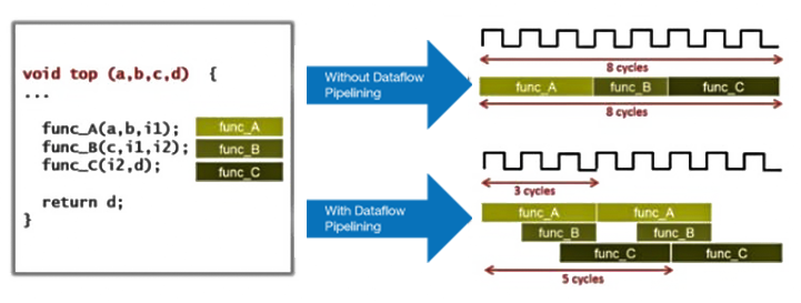
Figure 9: Pipelining at the data flow level
To help us optimize the C-based synthesis, we can use inbuilt design analysis tools to identify bottle necks, helping us to apply the correct optimization.
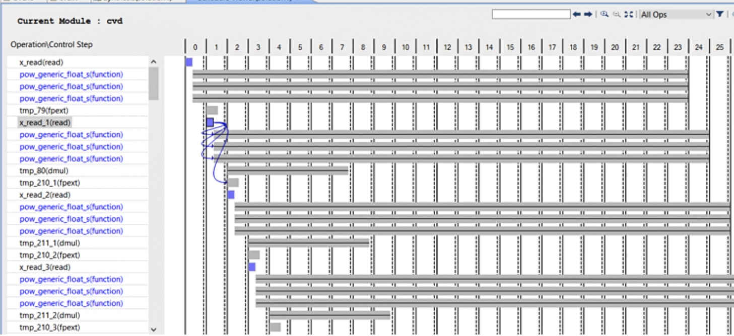
Figure 10: Optimizing the C-based synthesis with an inbuilt design analysis tool
9. System Optimizing Compilers
Many logic designs are implemented in heterogeneous SoC devices. These devices combine high performance processors (usually Arm based) with programmable logic.
Unfortunately, the standard development flow is based around separate flows, for the different halves of the device.
Once the sub system architecture has been defined, which identifies which elements of the algorithm are implemented in the processing system and which ones are implemented within the programmable logic, the two separate design and implementation teams go away and work in isolation until it is time to perform the integration at the system.
System optimising compilers enable the architecture of the design to be optimized and partitioned between the processors and programmable logic as the development progresses, seamlessly moving functions between the processor and programmable logic at will at the click of a switch.
This is possible thanks to the power of HLS and an interconnectivity framework which can connect HLS IP blocks back to the processor seamlessly.
This framework allows the application to be developed initially entirely running the processors cores in C. Again, like HLS this development flow is much faster, however, the resultant performance on the target, while functionally correct may not meet the performance required.
Like HLS tools, system optimising compilers are specific to a vendor. As such, for the rest of the section, we will use Xilinx SDSoC as an example tool.
SDSoC allows us to generate the design on the processor and then accelerate functions into the programmable logic using the following flow:
- Develop the application in C running on the processors
- Verify the functionality
- Identify the performance bottleneck functions
- Accelerate the bottleneck functions into the programmable logic
Once the application is complete, the TCF profiler can be used to identify the bottlenecks in performance. The results of this profiling can be used to identify potential acceleration candidates.
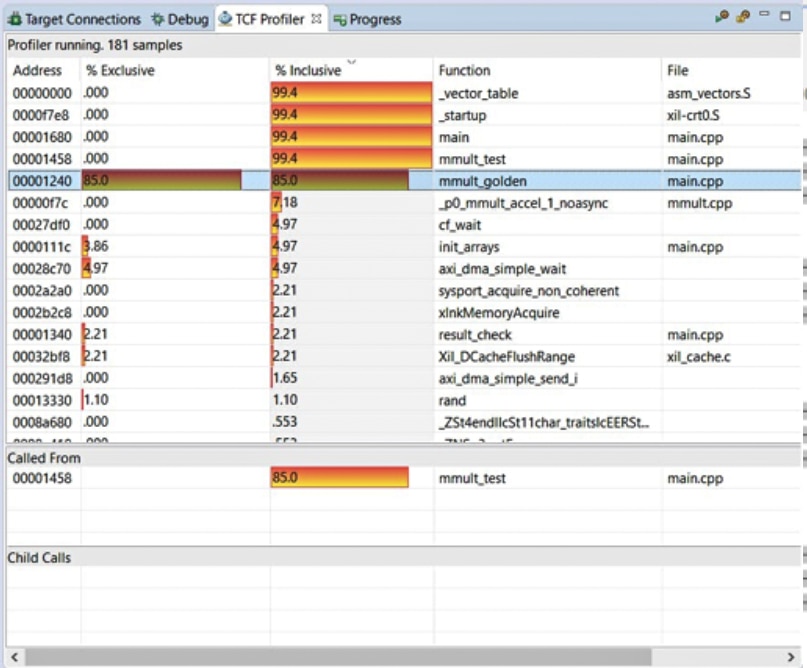
Figure 11: Profiling the Functions in SW
Once the application is complete, the TCF profiler can be used to identify the bottlenecks in performance. The results of this profiling can be used to identify potential acceleration candidates.
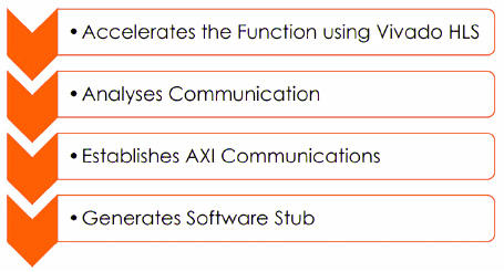
Figure 12: The stages that SDSoC uses to create a solution
As SDSoC uses High Level Synthesis as part of the solution, many of the pragmas used in an HLS solution are necessary to achieve the best performance in the accelerated function.
That may lead to the question of “What should we accelerate using the system optimizing compiler?” To get the best from SDSoC, we need to transfer large quantities of data to and from the programmable logic using DMA. If we are transferring small segments of data between the processor and programmable logic, the data transfer time will dominate and impact the results of the acceleration.
Amdahl's law can be used as a good indication of the acceleration achieved by moving a function from the PS to the PL.

Where,
S: overall performance improvement
α: percentage of the algorithm that can be sped up with hardware acceleration
1-α: percentage of the algorithm that cannot be improved
p: the speedup due to acceleration (%)
Set Alpha to 0.1 and select speed up - even with large acceleration P defined, speed up is close to 1
Set Alpha to 0.5 and select same speed up – close to factor of two improvement
Once we have an implementation, we may want to further fine tune the application. To provide the best understanding of the processor execution, data transfer time, and programmable logic implementation we can trace the design which provides a breakdown of where time is spent in the application.

Figure 13: SDSoC: Tracing the Design, looking in both HW and SW
10. MyHDL and CHISEL
Of course, not all developments use VHDL, Verilog, or HLS for development. There are several other languages which are often used for programmable logic development. Two of the more commonly used are CHISEL and MyHDL, and just like HLS tools both languages generate VHDL or Verilog for implementation.
According to the IEEE, Python is the hottest programming language. Python is used across several industries, taught in schools and universities, and even is used in embedded systems via micro Python.
MyHDL is a Python package that allows us to use Python to design our FPGA;, what’s more, it is open source and freely available. It is not, however, a High-Level Synthesis tool; the developer still needs to understand logic design techniques.
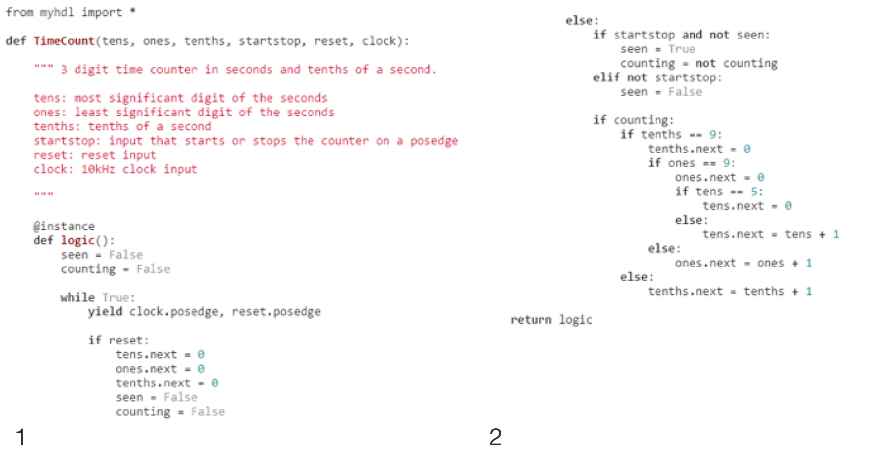
Figure 14: MyHDL Example
Like using HLS, MyHDL allows us to use the same language for the algorithm development as for implementation. To achieve concurrency, MyHDL uses generators, while communication between concurrent modules uses an object called a signal which is within the MyHDL package.
What is very interesting about MyHDL is that it provides a powerful simulation environment, as it can leverage the power of the wider Python language to generate test benches and stimulus. This includes native support for databases, GUIs, and so on.
CHISEL is an acronym like VHDL; it actually stands for Constructing Hardware In a Scala Embedded language. CHISEL is an open source language which was developed at UC Berkeley, the same University who gave us SPICE. Indeed, the RISC-V rocket core is implemented by Berkeley Architecture Research using CHISEL.
At the heart of CHISEL is SCALA, which was developed originally by a French university to compile down to byte code and be executed on the Java Virtual Machine (JVM). Within the programmable logic world, we use CHISEL very similarly to MyHDL although there are some subtle differences. The first is that CHISEL is object orientated, and the second is in how we verify and use our CHISEL design.
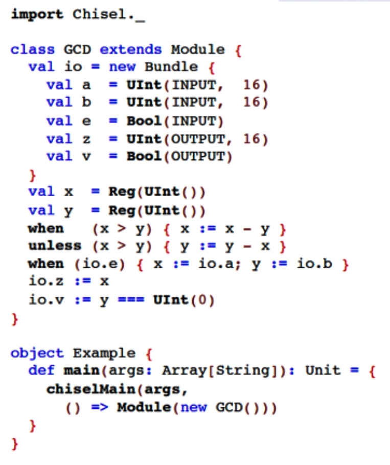
Figure 15: CHISEL Example
CHISEL has two output formats, but unlike MyHDL they are not Verilog and VHDL. Instead, Verilog's used for hardware implementation and C++ for verification, with the C++ being used for verification with a software model. This presents a very interesting capability for large designs, in that we can reduce the verification time significantly like we can when we are using HLS.
11. Higher Level Frameworks
When working with heterogeneous SoCs, we can use both processors and the programmable logic to implement the overall solution. We can of course use a system optimising compiler to implement the solution optimally between the processor and programmable logic. However, when we use a system optimising compiler, the software application is still created in C or C++.
What would be nice is to be able to leverage the design in the programmable logic using higher level languages and frameworks, such as Python, running on the processors.
One framework which enables this is the Xilinx Open Source PYNQ Framework. The PYNQ framework builds upon the Linux Kernel drivers and offers a range of specific APIs, which provide PYNQ libraries and drivers.
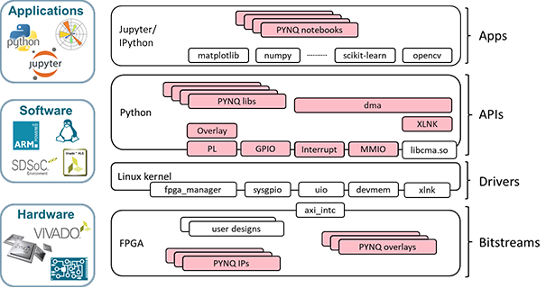
Figure 16: The PYNQ Framework
These APIs enable iPython applications running within a Jupyter note book to be able to access the programmable logic design.
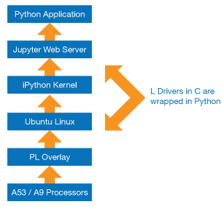
Figure 17: Implementation of the Pynq framework
Communication between the processor system and the programmable logic depends on the interface used. In PYNQ implementations, there are five different PS / PL interfaces which are used:
Free HLS Tools are generally specific to a vendor’s tool chain and devices. For the remainder of this section we use Xilinx Vivado HLS as the base example.
The standard development flow for an HLS based IP module is:
- Bitstream — This configures the programmable logic for the desired application. In the PYNQ framework, the xdevcfg driver is used.
- GPIO — This provides simple IO in both directions. In the PYNQ framework, this is supported by the sysgpio driver.
- Interrupts — Support interrupt generation from the programmable logic to the processing system. In the PYNQ framework, this is supported by the Userspace IO driver.
- Master AXI Interfaces — These are used to transfer data between the PS to the PL when the PS is the initiator of the transaction. The PYNQ framework uses devmem when employing the master AXI interface.
- Slave AXI Interfaces — These are used to transfer data between the PS and PL when the PL is the initiator of the transaction. The PYNQ framework uses xlnk to enable these transfers.
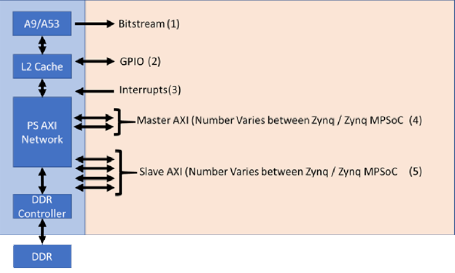
Figure 18: Interfaces between the processor system and the programmable logic.
PYNQ applications are developed using a Jupyter notebook over a web interface.

Figure 19: Example PYNQ code loading a design into the programmable logic
When it comes to creating PYNQ designs, we can use a system optimising compiler as the starting point to create the programmable logic design and the C libraries, which are then wrapped in Python.
Conclusion
Having been introduced to several languages which can be used to implement programmable logic designs, you should now understand a little more about the available languages and their suitability for your application.
*Trademark. Xilinx is a trademark of AMD Corp. Other logos, product and/or company names may be trademarks of their respective owners.
Shop our wide range of SoCs, EVMs, application specific kits, embedded development boards, and more. Shop Now
Test Your Knowledge
Are you ready to demonstrate your FPGA / Programmable SoC Programming Languages knowledge? Then take a quick 15-question multiple choice quiz to see how much you've learned from this module.
To earn the Programmable Devices III Badge, read through the module to learn all about FPGA / Programmable SoC Programming Languages, attain 100% in the quiz at the bottom, and leave us some feedback in the comments section.

