Surges are one of the leading causes of electrical device failures. The most dangerous surges are caused by lightning strikes, electrical operations on the distribution network, and industrial parasitic interference. A fault in one of these systems originating from a surge can have catastrophic consequences. In addition, the loss of operational capacity, services, data and productivity generally result in enormous costs, many times greater than the costs of surge protective devices.
The effects of overvoltage surges are fundamentally important in a world which has drastically increased the applications entrusted to electrical grids, IT and telecom networks. With miniaturization of circuits and components, modern equipment is more likely to be damaged by voltage surges than in the past. Thus, surge protection represents a fundamentally important topic to know and understand.
2. Objectives
Upon completion of this module, you will be able to:
 Define surge protection devices (SPDs) and their importance
 Describe the different classification types/classes of SPDs and their solutions
 Explain the operation of SPDs, their key features, and requirement specifications
 Discuss different application scenarios and use cases of SPDs
A transient surge is a sudden (shorter than a millisecond) rise in the flow of power. Voltage can peak at twelve times the nominal system voltage. Transient surges result from a number of sources, the most common of which are internal, such as load switching and even normal equipment operations. In fact, approximately 80% of transients are generated internally. External transients are the result of lightning and load switching by utilities and upstream facilities. These transients damage, degrade, or destroy electronic equipment. A surge protection device is a component that reduces the quantum of harmful energy flowing into a system. Surge protection is a huge topic to cover in a learning module, so the scope of this learning module is to cover the causes of power surges, their effects on electrical and electronic components, and how they are prevented using SPDs.
Large single surge events, like lightning, may reach hundreds of thousands of volts and cause immediate or intermittent equipment failure. Lightning and utility power anomalies, however, account for only 20% of transient surges. The remaining 80% of surge activity has internal origins, and is frequently caused by switching operations in power supply networks. These surges, although of smaller magnitude, occur in increasing frequency. Such continuous exposure deteriorates and reduces the functional life of sensitive equipment. Electronic equipment and data-processing systems users encounter operational and safety challenges in environments prone to high-risk transient overvoltage. Thus, effective surge protection is needed.
The "impulse withstand voltage," or resistance to transitory surges, plays a critical role in electrical and electronic equipment. It constitutes the reason for equipment to be protected with systems that isolate the parts connected to power phases from earth ground or neutral.
A surge protection device (SPD) is wired in parallel to the equipment it is intended to protect. Once the surge voltage exceeds its designed rating, it begins to clamp and starts to conduct energy directly to the electrical grounding system. In other words, the SPD, during a voltage surge, reduces its impedance within a few nanoseconds and diverts the impulse current.
The SPD behaves like a closed circuit; the overvoltage is short-circuited and limited to an acceptable value for the electrical equipment connected downstream. In general, SPDs have at least one non-linear component (spark gap, varistor or combination), and their function is to divert the discharge or impulse current and restrict the downstream equipment overvoltage. Once the surge is over, the SPD "opens" up. It does not trip upstream circuit breakers, and returns to its original impedance and open circuit condition.
- 4.1 UL 1449: Standard for Safety & Surge Protective Devices
The Standard for Safety for SPDs, UL 1449, was initially introduced as a standard for the safe installation of surge protective devices. It subsequently evolved to include performance standards of such devices based on particular wave test criteria. These criteria define specific test conditions and are integral to many standards, including Surge Protectors for Low-Voltage Installations NF EN 61643-11 (France), VDE 0675-6-11 (Germany), EN/IEC 61643-11 (Europe/International), and ANSI/IEEE C62.41-45 (USA/International). Some Telecom Equipment standards include IEC 61643-21, ITU-T recommendations, and UL 497 A/B/E. Global safety standards assess protection against surges (or transient overvoltage) as essential to good electrical system design. A summary is included within the IEC 60364 standard for electrical installations of buildings regarding SPD requirements.
The UL 1449, other than testing changes, is accepted as the ANSI standard ANSI/UL 1449-2006, giving it a much wider acceptance as manufacturing and testing criteria.
- 4.2 Causes of Transient Surges
Transient surges arising from lightning strikes and electrical network switching operations are principal causes of overvoltage. These overvoltages differ in amplitude, frequency, and duration. Transient overvoltage originates from four sources: lightning, power grid switching surges, electrostatic discharges (ESDs), and nuclear electromagnetic pulses (NEMPs).
a. Lightning
Two oppositely charged zones generate a lightning flash between them, typically between a cloud and the ground or between two storm clouds. The flash travels numerous miles, advancing in successive leaps toward the ground. The leader generates a highly ionized channel. When it touches the ground, the return stroke (or real flash or return stroke) takes place. Direct lightning may hit Lightning rods/conductors or external conductive elements (such as antennas and metallic pipes/guttering). Direct lightning strikes may cause severe damage, with crippling economic consequences.
When lightning directly hits a building equipped with a Lightning Protection System, the lightning current dissipates to the ground via the down conductors. The transient overvoltage, however, may propagate into the building via the earthing of the electrical installation. Such a direct effect may cause fire and damage equipment or the internal structure.
Transient overvoltage may also happen if indirect lightning strikes near the building or external lines linked to the structure. If this happens, the electromagnetic field created by the lightning will generate inductive and resistive couplings, leading to severe installation or equipment malfunction or damages.
b. Power Grid Switching
Innumerable daily transients stress electrical and electronic equipment on the power supply grid network via switching operations. Although switching transients have a lower magnitude compared to lighting transients, they occur frequently, and equipment failures can subsequently occur. Unforeseen loads modification results in sudden current variations (di/dt), which generate transient voltage surges. The brief duration of such surges, the sharp rising edge, and the peak value (touching several kV) result in premature electronic equipment degradation.
Figure 2: Switching of breakers (1) closed-circuit (2) the opening of the circuit.
Figure 3 shows a representation of different disturbances on an AC electricity supply’s power grid: A- Harmonics, B- Micro-interruptions, C- Surges from switching, D- Indirect lightning strikes, and E- Direct lightning strikes.
Figure 3: Representation of the order of magnitude of disturbances on an AC electricity supply grid
c. Electrostatic discharges (ESDs)
The electrical capacitance of a human being ranges from 100 to 300 pF. A walk on a carpet may accumulate a 15kV charge. This potential takes a few nanoseconds to be discharged with ten amperes current. Integrated circuits are susceptible to such disturbances, but the threat is easily eliminated with proper grounding and shielding.
d. Nuclear electromagnetic pulses (NEMPs)
A high-altitude nuclear explosion creates an intense electromagnetic field (up to 50 kV/m in 10ns) that radiates to the ground, affecting an area of up to 1,200 km in radius. The field induces significant transient overvoltages into power lines, antennas, and transmission lines, destroying linked sensitive electronic equipment. This field may be several kV/ns. Strengthened systems and reductive techniques help to eliminate electromagnetic pulse induced overvoltage. Shielding and filtering NEMP-adapted surge protectors can protect equipment from NEMP amplitude.
- 4.3 SPD Technology
SPDs are primarily made using one or more of these types of technologies: Spark gaps or gas discharge tubes, Metal Oxide Varistors (MOVs), Zener Diodes, or Silicon Avalanche Diodes. In this section we will discuss spark gaps, varistors and combination sparkgap-varistors.
SPDs Based on Spark Gaps:
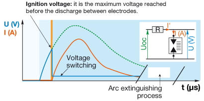
These are termed switching SPDs. The spark gap describes a component made of two mutually proximate electrodes that isolate one part of a circuit from the other to a specific voltage level. These electrodes can be in air, and in this case the spark gap fails to conduct current between two electrodes through the system (at rated voltage) during regular operation. The spark gap impedance, during voltage surge, quickly decreases to 0.1-1 Ω, with electric arc formation between the electrodes, generally in 100 ns. This electric arc gets extinguished when the surge concludes, restoring the isolation. A spark gap starts conducting when discharging. The spark gap's nature thus stops continuous current flow to earth.
Figure 4: Operational principles of spark gaps
Varistors
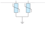
Metal Oxide Varistors (MOVs) are devices whose impedance is controlled by voltage, with an attribute continuous but not linear "U in the function of I." Varistor-based SPDs, also known as voltage limiting SPDs, are marked by high impedance when there is an absence of surge (generally above 1 MΩ). When a surge happens, the varistor's impedance quickly drops below 1Ω within nanoseconds, permitting flow. The varistor regains its properties of isolation after the surge discharges. The ground residual current, IPE, always flows through the varistors in the amount of 100 to 200 µA.
Figure 5: Characteristic curve and operation of a varistor-type SPD
The main characteristic of spark gaps is their capacity to manage large quantities of energy from direct lightning strikes, while varistors have a very low level of protection, and are therefore high-performance and are fast acting. Table 1 compares the differences between spark gaps and varistors.
| Varistor | Spark Gap | |
|---|---|---|
| Isolation properties | A varistor, although it presents a very high impedance at rest, always has a minimal continuous current, Ic, flowing through it (e.g. 0.5 NA). This current tends to increase as the varistor wears, until it reaches high levels. For this reason, Varistor SPDs must always be protected against short circuit and cannot be used for N-PE connection upstream of the RCDs. + include an internal protection that guarantees a safe end of life | A spark gap is a true open circuit when at rest, ensuring that there is no current flow at all either in normal operating conditions or when it reaches the end of its life; for this reason a SPD may be installed upstream of an RCD (therefore protecting it from the flow of impulse or discharge current) only if the connection between the active conductors and earth provides for a spark element. |
| Resistance when conducting | Even in the discharge phase, the resistance remains appreciably greater than zero, limiting the possibility to reduce the surge overvoltage to 3-4 times the rated mains voltage. | When the arc is ignited, the resistance becomes negligible. |
| Response Time | Very rapid, a few nanoseconds | Generally slow, but accelerated by the electronic device |
| Ignition / limiting voltage | Low, thanks to the fast response time | Low, thanks to the fast response time |
| Extinction of the short-circuit | Varistors are not characterized by a follow-through short circuit current, as their impedance returns to very high values as soon as the surge ceases. | SPDs with spark gap technology must necessarily be designed in a way that enables the interruption of the follow current (such as an arc extinguishing chamber). |
| End of Life | A varistor progressively loses its isolating performance; at the end of its life it can therefore become a low impedance short-circuit. | A spark gap is no longer able to ignite the arc at the end of its life, due to the wear of its electrodes or because the electronic ignition circuit has faded. It therefore becomes a permanently open circuit. |
| Need for back-up protection | Back up protection is necessary in order to ensure short circuit end of life safety. In case of short circuit end of life of the varistor the thermal disconnector is generally not able to open the circuit. | Back-up protection is to be provided for in all cases to ensure safety in the case of a fault with the SPD and to interrupt the electrical arc if the short-circuit current in the installation point is greater than the SPD's performance for interrupting the short-circuit follow-through current (Isc>If ). |
Table 1: Comparison of Spark Gaps and Varistors
From the comparison between varistors and spark gaps, it emerges that each has its own benefits and drawbacks. As a consequence, the best results are obtained, where possible, by combining the benefits of both technologies, using "combined technology" SPDs. The ABB Class 2 OVR T2 SPDs are available with combined technology to obtain maximum performance from both types of component. The combined varistor + spark gap solutions are suitable for protecting TT and TN-S networks (earthing) against indirect lightning strikes. (ABB offers multi-pole versions for each use.)
Figure 6: Combined Technology SPDs: ABB Class 2 OVR T2 Surge Protection Devices
- 4.4 Modes of Surge Protection
There are two modes of surge protection: common mode and differential mode.
Common mode: Overvoltages in common mode concern all neutral point connections. They occur between the live conductors and earth (e.g. phase/earth or neutral/earth). The neutral conductor is a live cable, as well as the phase conductors. This overvoltage mode destroys not only earthed equipment (Class I), but also non-earthed equipment (Class II), with insufficient electrical insulation (a few kilovolts) located close to an earthed mass. Class II equipment that is not situated close to an earthed mass is theoretically protected from this type of attack.
Differential mode: Overvoltages in differential mode circulate between the live phase/phase or phase/neutral conductors. They can cause considerable damage to any equipment connected to the electrical network, particularly "sensitive" equipment. These overvoltages concern TT earthing systems. They also affect TN-S systems if there is a significant difference in length between the neutral cable and the protective cable (PE).
Figure 7: Modes of Surge Protection
The UL-based SPDs are typically installed at three different points of a power distribution system:
 Service entrance: The point of entry for utility power. A unit installed here protects the facility from a large external event, such as lightning or grid switching.
 Mid-level distribution: Closer to the critical piece of equipment. A unit installed here protects from internally generated surges and isolates the critical equipment from faults.
 Panel board distribution: Installing surge protection on this equipment will extend its longevity by cleaning up mini surges that reduce equipment life.
The service entrance is the site of the utility power entry point, and the unit installed here protects the facility from any large external event, like lightning or grid switching. The typical voltage range is 480/277 V AC. The Mid-level distribution point is situated nearer to critical equipment. The unit installed here shields and isolates essential equipment from internally generated surges and protects from faults. The typical voltage range is 208/120 V AC. Installation of a surge protection unit on panel board distribution equipment will extend its longevity by cleaning up the mini surges that shorten equipment life.
- 5.1 Impulse Current Handling Capacity: 10/350 µs and 8/20 µs Waveforms
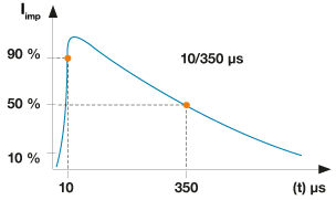
The impulse current handling capacity usually characterizes surge protection devices. The IEC 62305-1, 2006 and IEC 62305-4, 2006 specify two current impulse waveforms for testing of surge protective devices. The waveforms define their rise time and half peak width. They are referred to as 10/350 µs (Figure 8a) and 8/20 µs (Figure 8b) waveforms and are used in Class I and Class II SPD tests. The first number refers to the rise time (microseconds) of the current impulse to reach 90% of the peak level, and the second number gives the time to half value. The 10/350 µs waveform is for direct lightning strike tests, while the 8/20 µs waveform is for tests on indirect lightning strikes and surges caused by operations on the electrical grid.
Figure 8: Current test waveforms (a) 10/350 µs impulse and (b) 8/20 µs impulse
- 5.2 Lightning Protection Zones
The IEC standard introduced the concept of Lightning Protection Zones (LPZs) to help select the proper surge protection. This concept entails a gradual, staged reduction of energies and overvoltage caused by lightning or switching operations. This coordinated logic of protection is termed "stepping protection" and consists of internal and external zones. Externally, it has the LPZ 0A, which is unprotected zone outside the building subject to direct lightning strikes, and LPZ 0B Zone, which is protected against direct lightning strikes by external air terminal. The different protection zones are shown in the Figure 9.
Figure 9: Lightning Protection Zones
Internal zones are inside the building, which are protected against direct lightning flashes. The LPZ 1 Zone is subject to partial lightning or surge currents. The LPZ 2...nth Zone is where the surge current is limited by current sharing and where the surge energy is reduced by additional surge protection like SPDs.
- 5.3 Classes and Types of SPDs
The consequences of direct and indirect lightning strikes are different, and two separate devices are necessary for system protection. All SPDs are tested by repeatedly subjecting them to current and voltage impulses. An SPD tested with a 10/350 µs waveform is given the name Type or Class 1, and an SPD tried with 8/20 µs waveform is named Type or Class 2.
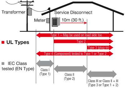
The UL 1449 categorizes SPDs into five types, based on their installed location within an electrical system. While Type 1, Type 2, and Type 3 categories refer to different SPDs installed at specific locations, Type 4 and Type 5 categories refer to components used in an SPD configuration.
Type 1 SPD: These SPDs are permanently connected devices installed anywhere between the secondary of the utility service transformer and the main distribution disconnect. A Type 1 SPD can be installed anywhere on the load side of the main distribution, and can be done without any external overcurrent protection requirements.
Type 2 SPD: These SPDs are permanently connected devices that must be installed on the load side of the main distribution disconnect. Type 2 devices may or may not require external over current protection.
Type 3 SPD: These SPDs are installed at a 10 meter (30 ft) conductor length distant from the protected electrical panel. Such devices are typically cord connected, direct plug-in, receptacle type SPDs installed at the protected load equipment.
Type 4 SPD: These SPDs are considered component SPDs. Component SPDs typically consist of one or multiple Type 5 components assembled. Type 4 SPDs are not intended for sole use, and must be integrated into other systems.
 A Type 1 component assembly is a Type 4 SPD that, once installed inside another piece of equipment, would be tested as a Type 1 SPD (external overcurrent protection not needed).
 A Type 2 component assembly is a Type 4 SPD that, once installed inside another piece of equipment, would be tested as a Type 2 SPD (external overcurrent protection needed).
Type 5 SPD: These SPDs are discrete component surge suppressors (like MOVs). These are mounted on a printed circuit board, connected by leads, or provided within an enclosure with mounting means and wiring terminations. Based on the IEC standards Class 1 and Class 2, SPDs are complementary, ensuring protection from the plant's origin point right up to the terminal devices.
| Type or Class | Class 1 | Class 2 | Class 1 and 2 |
|---|---|---|---|
| Test | Tested with 10/350 µs impulses | Tested with 8/20 µs impulses | Tested both with impulse currents 10/350 µs waves and discharges of 8/20 µs waves. |
| Use | Protect against impulse currents from lightning which enter the system directly, for example through the lightning rod or the aerial electricity lines. | Protect against surges induced by lightning hitting the building or surrounding area from surges resulting from operations on the electricity grid. | Protect against both direct and indirect lightning strikes. Used in small systems containing sensitive equipment (e.g. telecommunications). |
| Composition | Usually with spark-gaps or power varistor. | Usually with varistors, combined versions (varistor + spark gap) may be installed upstream of the RCD. | Usually combined technology (varistor + spark gap) |
| Installation point | Installed at the origin of the system. | Installed in all electrical switchboard of the plant, near sensitive equipment. | Installed in a reduced space at the origin of the plant, near delicate equipment. |
Table 2: Comparison of Class 1 and Class 2 SPDs.
Class 1 SPDs shield from direct lightning strikes, and are able to divert energy in larger quantities. Only a small part of the impulse current makes its way into the system and is subsequently managed by protection devices (Class 2).
A Class 2 SPD must be installed downstream of the Class 1 SPDs to protect sensitive equipment. The Class 2 SPDs protect against indirect lightning strikes and are designed to protect from multiple discharges, swiftly and with a high level of protection. They are installed near protected equipment.
Figure 10: Typical locations for SPD installation
Considering general-purpose applications as outlined in the IEEE standards, for a service entrance, a Type 1 SPD is needed with a surge current rating greater than 200 kA/mode. For secondary distribution, a Type 1 or Type 2 SPD is needed with a surge current rating greater than 80 kA/mode. For branch and point of use, a Type 2 SPD is needed with a surge current rating greater than 60 kA/mode.
- 5.4 Applications
In this section, we will discuss some SPD applications, using ABB’s line of surge protection devices as an example. The ABB OVR data/telecom SPD range is designed to protect equipment connected to data and telephone lines, to complement the OVR power SPD products and offer a complete system protection solution (power and data) against surges. The range includes protection for twisted pair data lines, computer networks, telecom systems including PBX and ISDN, CCTV, TV, and RF systems. OVR TC SPDs are protection for telephonic equipment, IT equipment, and BUS systems connected to low-voltage signal lines.
a. Protection for TV, Satellite, and Radio Systems
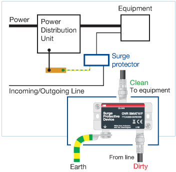
OVR TV Series protectors provide combined Category B, C, and D tested protection (to BS EN/IEC 61643-21), suitable for use on analog and digital Cable, Terrestrial and Satellite TV systems, including 4K high definition TV. These are connected in series with the coaxial cable at locations where they enter or leave each building, or close to the equipment.
Figure 11: OVR TV Series protector installation diagram
The line end is connected to the entering or exiting coaxial cable, with the clean end connected to the equipment. Cables connected to the protector's clean end should never be routed next to the dirty line end or the earth bond, to avoid transients being re-introduced after the protector.
The OVR TV/EURO and the OVR TV/F can protect standard un-amplified TV aerial feeds, whether the feed is for analog or digital reception. The OVR CATV/F can shield both Cable TV and Broadband Internet cable feeds. The OVR MATV/F is a wideband surge protector, as it covers combined signals from radio, terrestrial, cable, and satellite TV feeds for distribution systems. These are generally used in hotels and for public entertainment purposes. Ideally, an aerial feed or satellite feed should be protected at the entry point to the building before it is connected to an MATV system. The OVR SMATV/F is suitable for satellite TV feed protection.
b. Protection for Solar Power/PV (Photovoltaic) Systems
Lightning strikes may severely affect a PV plant's safety and performance. When a lightning strike hits the ground, the discharged energy affects the ground electrical field. In this environment, a solar PV plant is vulnerable to two risks: first, a direct impact that can physically destroy the solar equipment on a rooftop, and second, transitory overvoltages that pass through cables by magnetic coupling, which may damage sensitive components.
Figure 12: Photovoltaic Surge Protector for Solar Power System
In PV plants, the challenge is to choose the appropriate surge protection to withstand pure energy 10/350µs waveform currents, which are almost ten times more potent than type 2 8/20µs waveforms, while simultaneously taking space into account. The area is invariably a top priority inside a junction or inverter box. To maximize the available volume, ABB's SPDs use the depth of the enclosure for more robust components, with an increased depth of the device. With the new OVR PV QuickSafe series, both AC and DC circuit protection boards in solar installations can be protected against overvoltages due to lightning strikes or network disturbances.
- 5.5 MOV: End of Life
At the end of life of an MOV in normal conditions, the current passing through the MOV increases progressively, creating a quick temperature increase. This phenomenon will slowly damage the MOV itself, until it gets into short circuit. This phenomenon is called a thermal runaway. In order to avoid such thermal runaways, ABB has added a thermal disconnection that will detect this temperature increase and will open the circuit.
This disconnection QuickSafe is directly welded into the surface of the MOV to allow a very fast detection of the rise in temperature, so that it will react by opening the circuit when the temperature achieves the levels considered hazardous for the installation. This disconnection is guaranteed by a metallic arm linked to a spring, guaranteeing a quick disconnection. This is a phenomenon that happens only after thousands of surge protection interventions, on average. Most SPDs get changed during installation updates before this ever happens. This is the ultimate protection at the very end of life of the SPD.
 Electromagnetic interference (EMI): Frequency voltage disturbance that affects sensitive electrical circuitry due to electromagnetic conduction or radiation emitted from an external source.
 Harmonics: When any electrical power system witnesses non-linear loading due to voltage and current distortions, it is called harmonics.
 Impulse Current for Test Class I: This is the discharge current with 10/350 µs waveform that the device is able to divert towards earth or the network at least one time, without deterioration. It is used to classify the surge protection devices in test class 1 (the 10/350 µs waveform corresponds to this definition).
 Joule rating: A joule is the amount of electrical energy equal to work done when one-ampere current is passed through a one-ohm resistance for one second.
 Maximum discharge current (Imax): Peak current value of an 8/20 waveform that can be safely discharged by the SPD, with an amplitude in compliance with class II operating test sequence.
 Nominal discharge current (IN): The peak value of the current, selected by the manufacturer, impressed through the SPD, having a current wave shape of 8/20 ms where the SPD remains functional after 15 applied surges.
 Short circuit current rating (SCCR): The level at which an SPD is suitable for use on an AC power circuit capable of delivering not more than the root-mean-square symmetrical current at a declared voltage during short circuit condition.
 Silicon avalanche diode (SAD): These are semiconductor-type SPD components with fast, linear response characteristics, but which are limited by their energy handling capabilities.
 Surge Protective Device (SPD): A device designed to limit transitory overvoltage surges and to divert impulse currents away. Also known as limiters, they include at least one non-linear (non-ohmic) component. The international reference standards are IEC EN 61643-11 e IEC 61643-1.
 TT, TN-S, TN-C and IT system: They are different earthing system describing the connection to earth of the electrical system and its equipment earths.
- TT system: The electrical supply neutral is connected to earth. The exposed conductive parts of the system are connected to an earth bar.
- TN-C system: The electrical supply neutral is connected to earth. The neutral conductor and the protective conductor are the same conductor-PEN.
- TN-S system: The neutral and the protective conductor are separate and connected to the same earthing system.
- IT system: The neutral may be isolated from earth, or else connected to it via an impedance (from 1000 to 2000 ohms).
 Type 1 surge protective device (SPD): Surge protective device designed to divert the energy associated with a direct lightning strike or an operation on the electricity grid. The test parameter is the discharge current represented by a 10/350 µs waveform (test class I).
 Type 2 surge protective device (SPD): Surge protective device designed to discharge the energy associated with an indirect lightning strike or an operation on the electricity grid. The test parameter is the discharge current idem 8/20 µs waveform (test class II).
 Voltage protection rating (VPR): The value determined as the nearest highest value, taken from table 63.1 of ANSI/UL 1449 3rd edition to the measured limiting voltage determined during a transient voltage surge suppression test using the combination wave generator at a setting of 6 kV, three kA.
 1.2/50 µs impulse voltage: Standardized voltage waveform, which is added to the rated mains voltage.
 8/20 µs waveform: Standardized current waveform; it flows through the equipment at the moment it is subjected to an indirect lightning strike.
*Trademark. ABB is a trademark of ABB Ltd. Other logos, product and/or company names may be trademarks of their respective owners.
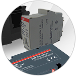
Shop our wide range of surge protection solutions, including mains surge protectors, data/signal surge protectors, and CAT-5E surge protectors.
Test Your KnowledgeBack to Top
Are you ready to demonstrate your Surge Protection knowledge? Then take this 15-question quiz to see how much you've learned.
To earn the Circuit Protection III Badge, read through the learning module, attain 100% on the Quiz, leave us some feedback in the comments section, and give the learning module a star rating.


