Take the Poll | Join our Discussion
sponsored by

Connecting an IoT System
The benefits of using smart technology for monitoring and automation are becoming more and more recognized. Existing applications are expanding their use of smart systems, whilst new applications are being released that benefit from this technology. Just some of the industries and applications include:
- Industrial Controls and Process Monitoring
- Smart Farming
- Marine Agriculture (Fish, Shrimp farming)
- Laboratory Instrumentation
- Car Parks
- Smart Offices
- Home Automation
There are many technological advances which have helped make smart technology more attractive and useful. Two significant ones are in sensor technology and in output driver/device technology. Sensor development has seen huge investment from a wide variety of industries and application areas, and this has led to improvements in the accuracy and robustness of existing sensors, as well as the development of sensors for new types of measurements and new applications. Similarly, actuator/output devices which can be used to control lighting, motors, transmit signals, and control all kinds of output devices have also seen significant development and are more compact, efficient, feature rich, and fault tolerant.
One big challenge, however, is how to connect these devices to work together. At a system level, it is often the case that individual sensor instruments do their job well, but do not integrate well as an overall system with other devices being used alongside them. Additional difficulties are often encountered where the system covers a large area.
Connectivity Challenges
An IoT system typically consists of three pieces: the sensors and actuators at the network edge, a gateway, and the cloud. The sensors gather data and send it to the gateway, which then hands it over to the cloud. The cloud performs processing and analysis; however, many gateways are intelligent and can handle preliminary processing duties, reducing the amount of data transferred and improving response time. Control messages travel in the opposite direction, flowing from cloud to gateway to the sensors/actuators. The cloud also prepares the data for human consumption, either displayed on dashboards or sent via SMS or email alerts.
There are many challenges in building an IoT system, including:
- Different interface types: Sensor and actuator ICs and modules use a variety of electrical interfaces (some based upon standard interface types and others proprietary)
- Different Protocols: Even on standard physical interfaces, the protocol varies between different manufacturers and models (data messaging format, for example)
- Distance: Many common interface types are for short range connections only
- Configuration and Data Processing: Most sensor devices need to be configured (and may need calibration and post-processing on the result) to perform their function
- Power Supply Requirements: Different sensors and actuators have different power supply requirements, requiring separate cable runs or local power sockets
- Cabling and Connectors: Sensors often have different cable type requirements, as well as custom connector types
Wireless sensors are most often impractical, because industrial settings are typically constructed of steel and concrete, which reduce signal strength. The machinery in industrial settings also generate a great deal of EMI noise, which can interfere with wireless communications. For most industrial applications, a wireline system is the most practical, secure, and reliable.
In many applications which could see huge benefit from smart technology, these challenges can add a significant expense and inconvenience for installation, detracting from the benefits or even be a blocking point to the adoption of smart devices.
Advantages of a Common Architecture
Urban Farm Greenhouse
In the simple Urban Farm greenhouse illustrated below, a common network is used to connect a variety of sensors and actuator devices. In this case, they are used for tasks such as monitoring the soil conditions, monitoring the air conditions inside, monitoring the weather outside, in addition to checking for motion and controlling lighting, monitoring the water and nutrient tanks, and controlling shades and awnings.
By working together on a common network, the cabling and power requirements are simplified significantly, and the system can be monitored and controlled from a single station. As all sensor and control data goes through one standard bus, the monitoring can also be done remotely without the use of many different networks and applications on a phone or remote computer for example. Additionally, it is much easier to control devices based on sensor inputs (for example actuating a shade based on the brightness and temperature) as both the sensors and actuators are on the same system.
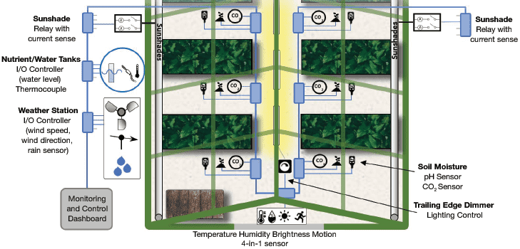
Figure 1: Urban Farm Greenhouse
Source: Bridgetek
Aquaculture
Aquaculture/marine applications can also benefit similarly by using sensors connected to an IoT system. Water quality is of utmost importance in marine applications. Characteristics such as pH, water temperature, oxygen reduction potential, turbidity, and nitrite and ammonia content must be constantly monitored, in addition to salinity for saltwater applications. Motion detection can also be helpful for detecting aquatic life as well as water flow.
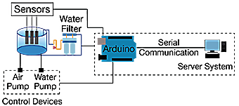
Figure 2: Aquaculture IoT System
Source: Karim, Hussain, Hassan, Iqbai, MNS Univ. of Agriculture
In the proposed system, sensors present in the water tank are connected to an Arduino, which serves as the gateway to a server. The Arduino is also connected to actuators controlling air and water pumps, and the system can control them as needed. The server processes the data, sending instructions to the Arduino, which relays them to the actuators. The server also prepares the data for human consumption, allowing the dashboard and alerts to be viewed on a desktop or mobile device.
Bridgetek LDSBus
Bridgetek have developed the Long Distance Sensor (LDS) Bus to help overcome the aforementioned challenges associated with using a large number of sensors together over long distance. The LDSBus comprises of three main parts:
- Long Distance Sensor Units (LDSUs): A range of sensor and actuator devices which share a common standard LDSBus interface
- Long Distance Sensor Bus (LDSBus): A modular and flexible bus which allows LDSUs to be connected over long distances
- Host Platform: A range of host platforms can be used which control the bus and communicate with the LDSUs over the bus to take readings and control devices
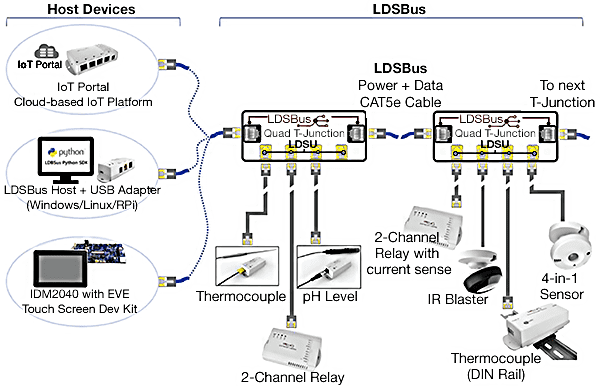
Figure 3: LDSBus Example System
The LDSBus is based on RS485 signaling which is both cost effective and suited for long distance communication. The use of CAT5e cabling with RJ45 connectors means that the cabling is easy to obtain and familiar to users and installers. Additionally, the RS485 standard and cabling has a long track record for reliability, even with long cabling distances. The single cable carries both power and data, simplifying installations. The protocol ensures that all devices can co-exist on the bus without conflict. Sensors and actuators can be added at any point on the bus and in any order.
Internet of Things
Shop our wide variety of MCUs and IoT products from Bridgetek.
Don't forget to take our poll.
The LDSBus uses T-Junctions, which are daisy chained along the length of the bus. They can be inserted at any point along the bus to tap into the power and signal lines. The host system connects to the first T-Junction and the pass-through connection is used to link to other junctions . T-Junctions simplify the install and make it easy to expand the system.
Each T-junction provides four RJ11/12 ports. An LDSU sensor or actuator module can be connected to each RJ11/12 port. The LDSU cable can be up to 5 meters long using RJ11/12 to RJ11/12 cables (or RJ11/12 to JST connector for some LDSUs). A single run can extend for up to 200m in each direction using RS485 signaling, allowing a 400m wide area to be covered.
A sensor/actuator LDSU can contain more than one sensor using only a single RJ11/12 port. For example, the 4-in-1 sensor comprises Motion, Temperature, Humidity and Brightness sensors, while the 2-channel relay with current sense actuator module has two relays and two current sense channels in one unit.
All T-Junctions and sensors/actuators are housed in robust enclosures and have a variety of built-in mounting options.
Power on the LDSBus runs at 24VDC to avoid issues with voltage drop over long runs, as well as to allow a reduced current. The T-Junction includes a regulator so that the higher voltage can be regulated to 5V for the four sensor ports. Sharing the same power source reduces complications in installation.
Since every device uses the same signaling protocol, there is never any issue with compatibility. All system monitoring takes place through the same user dashboard, monitoring the bus and polling the intelligent LDSU nodes to check their status.
LDSU Sensors and Actuators
The intelligent Long Distance Sensor Unit modules have a built-in microcontroller which provides the bridge between the LDSBus and the sensor or actuator integrated circuit. This allows the LDSU to configure the sensor IC over its local interface (often a protocol such as I2C or SPI). It also allows calibration data to be stored, as well as any processing of the data specific to the sensor/actuator type to be carried out. This helps avoid a lot of workload on the LDSBus host as the data is already in a useable form. For example, it can provide linearization of the data read from a temperature or pH sensor or can create dimmer curves on a trailing edge dimmer actuator for lighting.
The on-board MCU can also provide functions such as monitoring the power supply and reporting expected device characteristics back over the bus such as current consumption and friendly name for easy identification (which can be configured using the LDSBus Configuration Utility when setting up the system). The status LED is very useful for setting up and checking that the unit is operating correctly.
In the example shown below, the T-Junction is connected in-line with the LDSBus and provides a tap from the RS485 data lines as well as 5V power through the RJ11/12 cable to the sensor unit. The LDSU contains the bus transceiver, power filtering and monitoring, the MCU, and the sensor IC itself. Depending on the type of sensor, the sensing itself may be on-board the LDSU or may use an external probe (in the case of the thermocouple or pH probe for example).
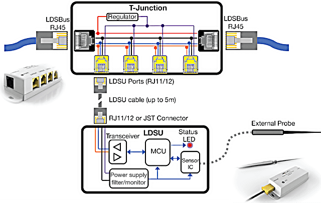
Figure 4: LDSBus T-Junction
Some examples of available sensors/actuators from Bridgetek are shown in the illustration below:
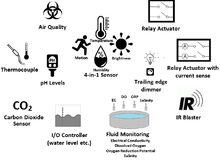
Figure 5: LDSBus Compatible Sensors and Relays
Summing Up: Connecting It All Together
Adoption of IoT will continue to grow significantly in both existing and new applications. As installations become larger and more comprehensive, and as new areas of industry begin to consider smart technology, connecting the components of these systems is one of the major challenges that engineers are facing. Bridgetek’s LDSBus provides a solution for connecting the components of a large-scale IoT system over long distances.
